Hello
Hello, my name is Beanie Hakki. I’m a transfer student from a small school called Alderson Broaddus University in Philippi, West Virginia. I’m from Richmond, Virginia, and this will be my third year at JMU. I originally majored in Business Administration but after my first semester, I quickly changed my major to Biology. At the end of this semester, however, I plan to add Chemistry as a minor. After JMU, I plan to attend Liberty University to get a degree in Biomedicine and I hope to attend medical school soon after!
I was an all-star cheerleader for 13 years which allowed me to accept an athletic scholarship to be on an Acrobatics and Tumbling team at AB, and to be on JMU’s Cheer team for one year. I enjoyed all my years as an athlete but my joints have some regrets when it rains. Now I stay active by working out in the gym and playing soccer with friends at a local recreational sports center during the summer. Some of my other hobbies include hanging out with my family and my dog, Aurora, playing video games (both PC and PS4), driving my car faster than I should while listing to my music too loud, and participating in the arts such as drawing/painting and playing the piano.
Some other interesting things about me is that my father and his side of the family are all from Cairo, Egypt. My dad also lived in France and use to race cars professionally throughout Europe for a while which is probably where I get my lead foot from. My mother and her family are from Southern Virginia, so I quite often make the joke that I’m a Redneck Egyptian because it’s such an unusual combination. I’m the oldest of three and our ages range from 21-23 years of age. My sibling and I are very close to each other due to how close we are in age. I’m also the funniest person I know.
I have no experience in 3D printing, but I hope to learn a lot and will be able to use 3D printers in the future. On the other hand, I do have a lot of experiences in puzzles! I LOVE puzzles! During breaks, or whenever I’m stressed and have some free time, I go and buy at least a 1000-piece puzzle and will sit hours on end working on it. I spent a lot of time playing with both a 3×3 and 4×4 Rubix Cubes, and now know how to solve both! Another thing I also enjoy doing, which contributes to my love of puzzles, is taking things apart and learning how to put them back together.

Also here’s a couple pictures of me and my dog. She loves piggy back rides and she’s kind of derpy but so lovable. 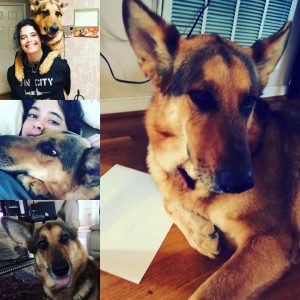
You can find me and follow me at these websites:
Initial Puzzle Research
This first puzzle I found by simply googling “wooden puzzles” and after scrolling for a bit one puzzle caught my eye. This puzzle is called Merkaba and is created by a man named Lee Krasnow. What stood out to me not only its shape but the fact that each piece is made of five intersecting tetrahedrons. When I first saw it, I wasn’t even sure if it was a real puzzle until I did some digging and found an article about Krasnow’s work which featured a video of how all of his puzzles work. How the Merkaba works is each joint of puzzle comes apart and moves together simultaneously which he called coordinate motion. I think it would be interesting to see what it would look like if instead of using tetrahedra use cubes or another shape or a combination of different shapes. I wouldn’t change how the puzzle is put together if possible. The way it is designed makes the puzzle look seamless almost as if it was made this way rather which adds to how interesting this puzzle is.
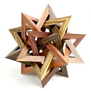
Photo Credit:
Lee Krasnow of Pacific Puzzleworks Makes Mind-Blowing Puzzles
And
Lee Rasnow’s Etsy pacificpuzzleworks
This next puzzle I’ve seen on twitter a couple of times and found it also on google. Unfortunately, I couldn’t determine who created it but I found the website that features it and many others like and the men and women who created them and where you can buy their puzzles. This puzzle is a box puzzle where the top of consist of moving parts that turn a specific way till the box opens up after which you can hide whatever is small enough to fit. The top of the box has designs on it and when you turn it, the end result that opens the box looks identical to how the box originally look making it extremely hard to figure out without instructions or a how-to video. If I were to modify this idea, I would have the end design be different than the beginning, not to make it easier to solve but because a box this unique shouldn’t be limited to one design. Another way I’d modify it would be maybe make the box bigger and created different compartments with different end designs opening a different compartment. Both would be hard, but I think it would add a lot of value to the box.

Photo Credit:
Tinkercad Cube Puzzle
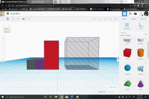
For my cube puzzle, I wanted to try and be as unique as possible. To be honest, I struggled for a while to come up with an idea that I liked or thought would work. Eventually I came to the idea of making a hollowed-out cube with parts that would fit together like puzzle pieces but with Tetris like shapes or triangles and other unusual parts that one wouldn’t usually see in cube puzzle. Originally, I thought coming up with the puzzle was the hardest part of this project; however, I have not figure out way to create this puzzle using Tinkercad which would result in my desired print. I first tried to use a cube as a template and see if I could manipulate the shapes and make holes in the cube, but that didn’t work as I had hoped. There were no outlines of the shapes that would create the actual pieces of the puzzle.
After that idea had failed, I again used the red cube as a template and tried again, but this time I put the pieces together using different shapes that Tinkcad had offered and went as far as going through all the shapes that they offered. I quickly determined that I also did not like the direction it was going in.
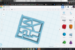
My final solution to this problem was to try and use the “Scribble” option. I have a Surface Pro computer with a pen which allowed me to draw directly on Tinkcad, making it easier for my idea to come to life. However, I didn’t know how to turn it into a cube with each side having different shapes and pieces. When drawing, it creates and very long edge that you can’t draw into without messing up what you already have and the only solution that I can think of is drawing each individual side seperatly. This solution will take a lot of time and I’m not even sure it would work because I want to have some pieces that extened to multiple sides in order for it all to fit together and hold its shape. I unfortunatly came up with this solution too late to try and print this out and won’t be able to provide a picture till later.

Thingiverse Puzzle Print
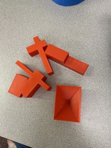
The puzzle I choose to print from Thingiverse is called Zimmermannsknoten/Carpenters Knot by wengeol2 AKA Oliver Wenger. I chose this puzzle because I’ve seen it before, and I’ve always wanted to own one and figure out how to put it together but never got around to it. Each piece was printed out all at once causing the size of the print to be quite large, resulting in a 7 hour and 22-minute print time. It was hard to find enough time in my schedule that allowed me to start the print and stay for the first few layers while also causing no conflicts with another class. I had to wait till Monday to print this out since there were no classes due to the holiday. Another option I had for this print was to print each individual piece by itself, rather than I as a whole. Mr. Wenger was kind enough to provide prints for both, however, I saw this method as too time consuming and difficult to fit with my schedule. A benefit to printing individual pieces of this puzzle was that if one of the pieces had failed to print properly, I wouldn’t have to redo the whole print, just that specific piece. This also contributed to why ended up choosing this print.
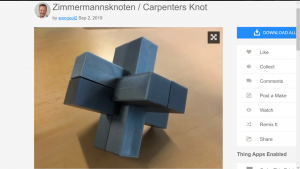
Photo and puzzle credit:
Zimmermannsknoten/Carpenters Knot by wengeol2
&
Cube Puzzle Wrap-Up
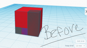
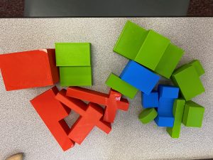
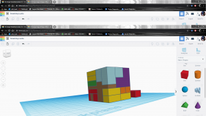
In order to wrap-up my Cube Puzzle, I trashed my original idea and created something drastically different. I did this because I couldn’t figure out how to make my original design in Tinkercad and make it printable. I simplified my design drastically. My new design incorporates shapes that I made and came up with, and the use of imported shapes. I took these shapes and made them into a puzzle by picking a piece that would be the starter piece and worked around it till it became a cube.To keep the cube proportional in size I used two red rectangles, one lying flat and the other standing up, as a reference. Continuing to build up, I wanted to keep the original idea of having interesting pieces, so I employed the use of the two arches with an oval in the middle and a pyramid. The oval that went in between the two arches was a difficult piece to create because no pieces in Tinkercad had already existed. So how it got this piece was I took the two arches and stacked them on top of each other. Then I took a cylinder and placed it on its side and sized it to be the exact same width of the arches and aligned it, then used the “hole” feature to get the oval. For the pyramid, I originally wanted to use different shaped wedges to surround it, however none of the wedges fit the pyramid right and it looked funky so I opted to use the hole feature again to have a cube surround the pyramid to create a secret or surprise pyramid.
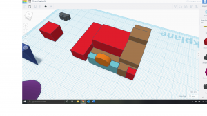
To try and avoid a potential spatial issue, I gave myself a 0.2-0.3 mm margin of error on each side of every piece. I originally was only going to do 0.1 mm and was also going to round each edge of every piece; however, I was unable to do that with the imported pieces, so upped the margin of error. When I was finished with creating the puzzle, I grouped the whole thing together and resized it to my desired size to keep all the pieces proportional. I had to do this twice, which I’ll explain why in a moment. When it came to printing my pieces, I laid them so that eh largest surface was facing down, so that it would hopefully avoid any print failure.

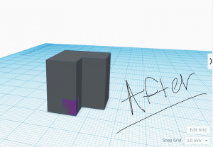
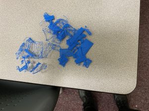
My first print immediately failed. I concluded that it failed because the pieces were too small, so that when the print head lifted, it took the pieces with it, instead of leaving them on the print table. To fix this, I put back together my puzzle, grouped it together, then enlarged it. Putting together puzzles on Tinkercad is painful. After enlarging it, I could no longer print my pieces in one print and had to do two separate prints. I stayed about two and half hours to make sure the print wouldn’t fail, and it looked like everything was fine. What I didn’t look out for was the amount of material the printer had. My larger print didn’t finish because it ran out of material in the middle of the night and I will be printing out again later today. Lesson learned, always look to see how much material you have before you print a large print. Luckily the smaller print was successful.

The main thing that I learned from this project, outside of how to use Tinkercad, was how to import shapes and other STL files into Tinkercad, and how to manipulate them. This feature will likely be used many times in further developing puzzles. Another useful thing that I learned form this is how to think in more of a three-dimensional mindset and how to apply that to the puzzle that I want to create.
You can find my puzzle at:
Personal Project Pitch
My personal final project was greatly inspired by a friend of mine’s little cousin. She is young and very ill, but she’s incredible smart and has huge knack for 3D puzzles. She has the capability to just look at the finished product picture on the box and somehow put the puzzle together, WITHOUT THE INSTRUCTIONS OR HELP. It was honestly amazing to watch. Another inspiration was my love for Legos growing up, and how Legos can be literally whatever you want with a little imagination and a lot of time. Recently, I saw that a group of people recreated The Battle of Helm’s Deep from The Lord of the Rings all in Legos. Between this, and my friend’s cousin, I concluded that I wanted my final project to be something brings these two ideas together yet reflects what I am interested in as a student. As a biology student, my main interest is in Neuroscience, so I want to make a 3D puzzle that at the end, looks like a brain.
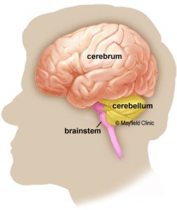
Photo credit:
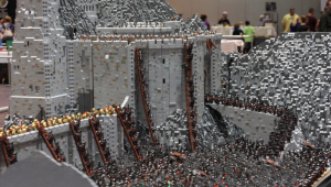
Photo credit:
Some previous knowledge that I used from my cube project will likely use a lot for this project is being able to import STL files. How I am most likely going to go about this project is that I will likely use the 3D scanner (with permission from the Makery) by creating the puzzle using outside media, such as clay, and scan it into an STL file and upload it to Tinkercad. From there I will edit or even adjust shapes as needed. I could also import the shape of the brain and take it apart, piece by piece, making the puzzle as I deconstruct.
How I will design the project is that I will start by making a prototype out of clay. I took two ceramics classes in high school and even though that was a long time ago, I feel that it will help me not only visualize my puzzle, but also be strong enough to scan when the time comes. My main concern with the puzzle is really the Cerebrum of the brain (the two hemispheres). The Cerebrum is highly convoluted and makes up the largest portion of the brain. How I will likely attack this is by creating the two hemispheres of the brain by creating balls of clay and shape them to look like a smooth brain when I put them together. I will wrap each side in saran wrap, so that they do not attach to each other, and roll up some clay and randomly drape them around the balls of clay. This is how I plan on making the pieces. I want to created the actual layout of the cerebrum then cut the cord at specific places, this way I know the pieces will fit together and the final product will look like a brain.
Originally, I had planned to attack the whole project like this, having both the inside of the brain and outside be made of the rods shaped in weird ways, but layered on top of each other. Another idea that I have, is just to keep the outside part the rod pieces, but the inside be created by Tetris-like or random shapes to create a solid structure for the cerebrum to rest on. This won’t likely be determined till later on based on whether or not it looks good or is even possible to do.
Aside from figuring out how to make my brain puzzle, I will likely have to learn programs outside of Tinkercad to be able to create this puzzle. I will be doing lots of research into this idea, and even see if there are other people who have done this idea, or something similar, and see how they went about creating their idea. My main issue I have is being able to take my idea from my brain and making it happen in Tinkercad or even on paper. Quite honestly, even learning how to make other puzzles that have nothing to do with how I want my puzzle to work could help me come up with a good way to create this. I have a feeling Youtube will be my best friend for this project. I also want this to be as anatomically correct as possible, so I will be doing a lot of research.
Digital Fabrication in the Makery
Overview:
In order to create my final project, I will be required to use the 3D scanner at the Makery. I am utilizing this scanner because parts of my project require a certain skill level to create the pieces of my Brain Puzzle that I will unlikely be able to acquire in time for the due date. To use the scanner, will create a real sized, working prototype containing each piece of my puzzle made out of clay. Afterwards, my prototype will be scanned as a stl file and uploaded to Tinkercad, to which I will adjust each piece as needed. Finally, I will print the uploaded stl final thus creating my second prototype.
Some important information to know about the brain and my puzzle:
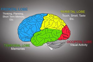
The brain consists of three parts: The Cerebrum, The Cerebellum, and The Brainstem. My puzzle will only include the cerebrum and the cerebellum due to structural reasons. The cerebrum can also be broken down into four lobes: The Frontal Lobe, Temporal Lobe, Occipital Lobe, and the Parietal Lobe. I mention the lobes of the brain because I have been playing with the idea that the pieces of the puzzle will create each lobe of the brain, which will then connect to each other with their own, larger notches. This will unlikely add to the difficulty to the puzzle but will allow the user to learn the different parts of the brain. It would be more of a “wow, fun fact!” rather than a “wow, this is hard!”
Photocredits:
Parts of the Brain (Left); Anatomy of the Brain
Parts of the Cerebrum (Right); What Is The Cerebrum? What Is Its Structure and Function?
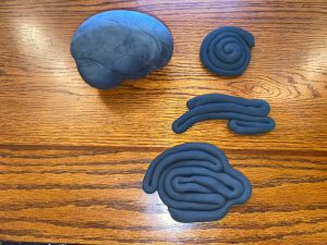
What I am making at the Makery:
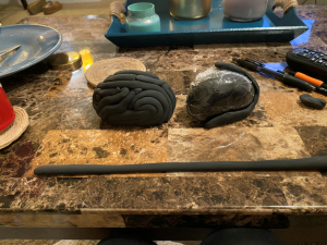
In order for the 3D scanner to be useful to my project, I must make sure I understand how it works and how much I will be able to manipulate the uploaded stl files retrieved from the scanner. With the limited experience I have with uploading stl files into Tinkercad, I realized that not only is it hard to adjust the uploaded files, but the adjustments are limited. To explore what I can adjust, I will be making a modified prototype. Instead of scanning the prototype all together as one unit (pictured on the left), I will separate the “pieces” of the cerebrum and the body (pictured on the right). I will then scan these pieces of the prototype, upload it to Tinkercad, and see what I can adjust and print it. *NOTE: These pieces are neither the actual size of each puzzle piece, nor shape. They are representations of how the pieces might look when they come together*
The uploads serve different purposes to my puzzle. First, it will allow me to see how much flexibility I will have with editing the size, shape, and over all fluidness of each piece. Second, it will allow me to see if I can create pieces out of the body once it is uploaded since body of the prototype has not been broken down into individual pieces. Lastly, this will allow me to see how well the prototype will work to create this puzzle, see if there are any limitations that the scanner might have, how much detail is picked up by the scanner, and to see how much disparity there will be between the prototype and the print of the stl file. This last one is very important because if I expect to get one out come, but get another, then it will have to severely change how my prototype will look in order to get my desired end result. It is also important because if there are any limitations with the scanner, or if the clay medium is insufficient as a prototype, I will need to know sooner, rather than later.
This print will not be my second prototype, but it will also contribute greatly in creating it. I will be using a similar, but more completed clay prototype to scan and then print. My second prototype I will likely cause me to make many alterations prior to the final print. The greatest adjustments that foresee myself making is that of special arrangements of the pieces to ensure that the puzzle will come together and come apart smoothly. I am also planning for the possibility that I will not be happy with the shape or certain cosmetic features of the prototype that will then change as I see fit.
The Process:
The only tool I will be using in the Makery is the 3D scanner. In order to use it, I will be requiring the help of the staff at the Makery. To do so, I had to set up an appointment with the Makery and came in with my prototype and my own flash drive. I placed each pieces on the scanner and allowed it to scan into the computer as a stl file and downloaded the file to my flash drive. Once I completed this task, I went upstairs to our lab and uploaded the files to Tinkercad and immediately printed what I had, without any adjustments. As I stated earlier, the most important part of this test was to see what, if any, differences there might be between the clay prototype and the finished 3D printed product. The best way to compare the two is the not make any adjustments AT ALL to the original stl file and compare the final print to the original prototype. Even though “ctrl z” is effective in deleting any alterations in the program, it is easier and more reliable to just go ahead and print what I have. Playing with how much I can adjust each piece can be done at any time, making it less important than the comparison.
What I Learned:
This test run was minor and can only show but so much. However, it gave me a general understanding of what I can manipulate in Tinkercad as well as how much changed between the clay prototype and the print of the scanned stl file. This knowledge will contribute to creating my final project greatly because now I can create a more sophisticated clay prototype which will soon lead me to entering the second phase of this project. The second phase consist of creating the second prototype, by creating my puzzle with accurate pieces, scanning it, uploading it to Tinkercad, then printing it. Knowing what I can change in Tinkercad, and what will have to be changed as clay will greatly decrease the amount of time I spend on creating the second prototype and allow more time to perfect my final project.