Project Summary
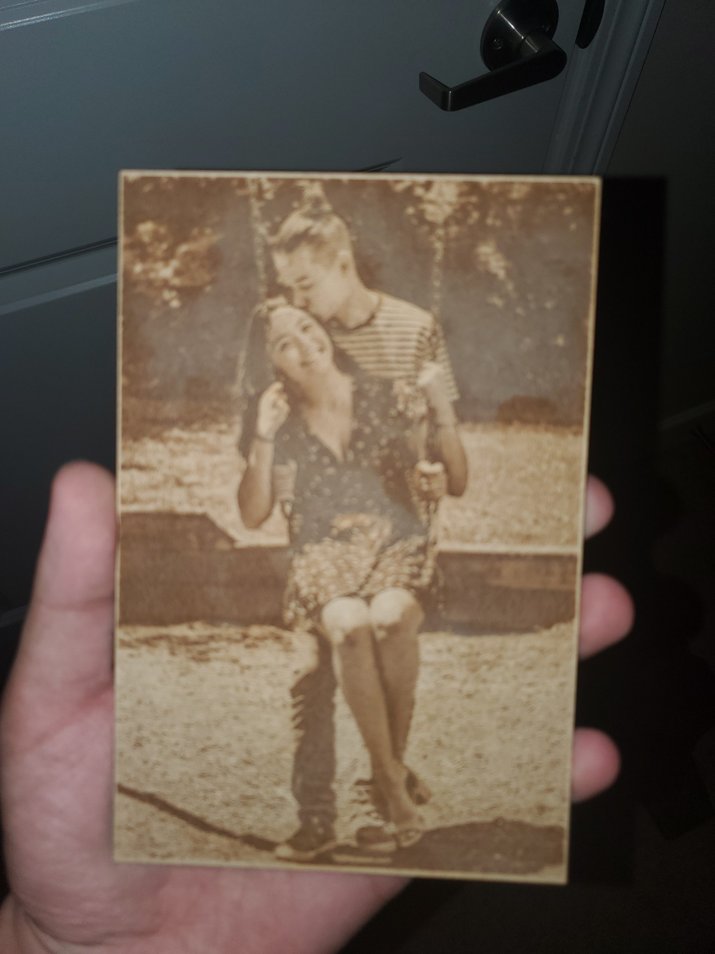
The idea behind this project is a puzzle which is an iteration of the classic hedgehog puzzle both with a different shaped prison and object contained within.
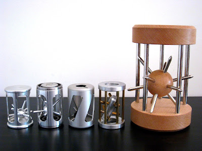
Photo Credit: http://smallpuzzlecollection.blogspot.com/2013/06/hedgehog-in-cage.html
Prototype
The thought process behind this prototype was to find an initial shape that can potentially have a unique way of fitting through a certain shaped hole. To start I chose the initial hole shape as a hexagon. I choose a hexagon mainly for the reason that I felt that it gave me plenty of freedom since there are a lot of potential shapes that could fit inside, however it also gave me some limitations. I felt that too much freedom when designing could also be a negative.
The hexagon I started with initially was a regular hexagon. In other words, each internal angle was 120 degrees. I chose this arbitrarily–however it got me thinking that I modified the hole shapes of my prison to have angle degrees slightly above and below 120, it may solve the issue of multiple solutions.
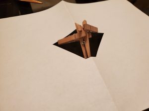
When it comes to my actual physical prototype, I cut a basic hole from a sheet of paper and connected 3 clothespins together to make a rudimentary 3D object. The purpose of this prototype was to see if I could make an orientation of the clothes pins fit within the semi-defined hole. I treated the clothespin object as the skeleton of the 3-D object–which I guess in this case would mean it would be a triangular pyramid.
After several paper cutting methods and attempts I was able to create such a hole where the base of this object just slightly is able to squeeze through without much manipulation. I’ve learned that from this process that style of puzzle is possible–given enough time to tinker. Some limitations to this prototype is that the full on cage is not constructed. I’d argue that this prototype is more of a proof-of-concept. In other words, I was primarily focused on making sure that my idea was plausible–instead of communicating the information behind my idea.

Initial Design Tests
After the original proof of concept which is mentioned above, I felt that the most logical step was to replicate something similar over cad, then adjust for tolerances. To do this work, I based my cad off of Fusion360. I felt this was the better choice over Tinkercad because the sketch tool in conjunction with the define tool can get me the complex shape that I need for that hole.
To make the shape I did rough measurements with calipers to get lengths that I would use to define my shape in Fusion360. This quickly translated into the 2D sketch shown below. The reason why the sketch is blue–or undefined, is because it is undefined in terms of positioning (which at this time is unimportant). I then surrounded, the figure with a rectangle which I then extruded to create the desired shape.
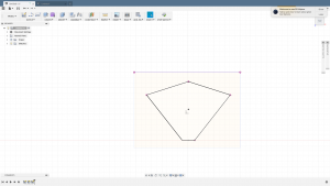
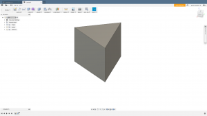
The second object that I created, was an equilateral triangular prism. I chose this as my initial basic shape for 2 main reasons. First, it mirrors the base of my original Proof of Concept. Second, this shape would take me little to no time to create in Fusion360 (in comparison to a triangular pyramid–which would require a construction plane), so I could easily iterate and iterate until, I found acceptable tolerances. To make my prism, I used the inscribed polygon tool to create the largest triangle that I could to fit within the pentagon above. Lastly, I extruded again–nothing fancy here!
When it came to actually printing the desired objects, luckily I had no problems with the printing aspect. However, issues arose when determining how snug I wanted the pieces. This was to be expected since this was the issue I intended to solve. I printed each object to scale as shown below.
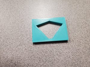
As you can see with the first prism, there is plenty of initial wiggle room. Second, you might notice that there are several orientations the piece could be placed at where a solution is possible–which told me I need to increase the size.
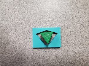
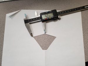
For solving this issue, I decided to go with the “brute force” method of slightly increasing and decreasing tolerances until I found something that I liked. For the second prism, I increased the scale by 10%. At this point I realized, that I only had to increase the dimensions in the x and y directions–this was a useful thought because it would save me time printing each prism. Luckily though, the 10% increase seemed to do the trick.

This picture shows the slight increase in size between the two triangles.
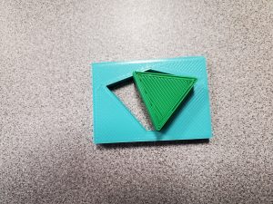
This time, there are only two possible solutions, which are is the current placement above as well as it mirrored on the other side. I felt that this was a great stopping point since I could then iterate the prism by sticking out rods etc. to get that 1 final solution.
I think the next logical scale to go from here is instead of a singular hole, have a replicable sheet created (Which is in the process of being made below). My thought process is that I should create a “cage” where all the holes are solutions to start. Then, from there, I can narrow my tolerances on all holes but one to create a single solution. The part that I think will cause me the greatest difficulty going from here is whether or not to design 4 individual panels that assemble, or one completed structure. Currently, I am leaning towards the side of the 4 panels.

Another route that I could go, or do in tandem, is to create what I would want the final shape to look like and test its ability to go through the pentagonal hole. Currently, I am not sure how I want this final piece to look like other than the fact that it will be triangle based.
Initial Design Tests #2
For this series of design tests I decided to focus on a more minute detail of my puzzle–Logo design. I know regardless of how my puzzle turns out, I would like to build a container for it. I was thinking that the best container for this would be made out of wood (potentially using the Glowforge). So I took the time to familiarize myself with the Glowforge software and laser engraving process.
To create this simple laser engraved photo, I first edited this photo in Photoshop. This process was relatively simple since I have experience with Photoshop already. Essentially, I scaled my image, converted it to black and white, then optimized the exposure. Last, I increased the contrast then sharpened the image.
Afterwards, I imported the Photoshop file into Illustrator, created a empty box around it for the cut, then exported the file as an SVG.
My initial logo design is something below (Rough Sketch):
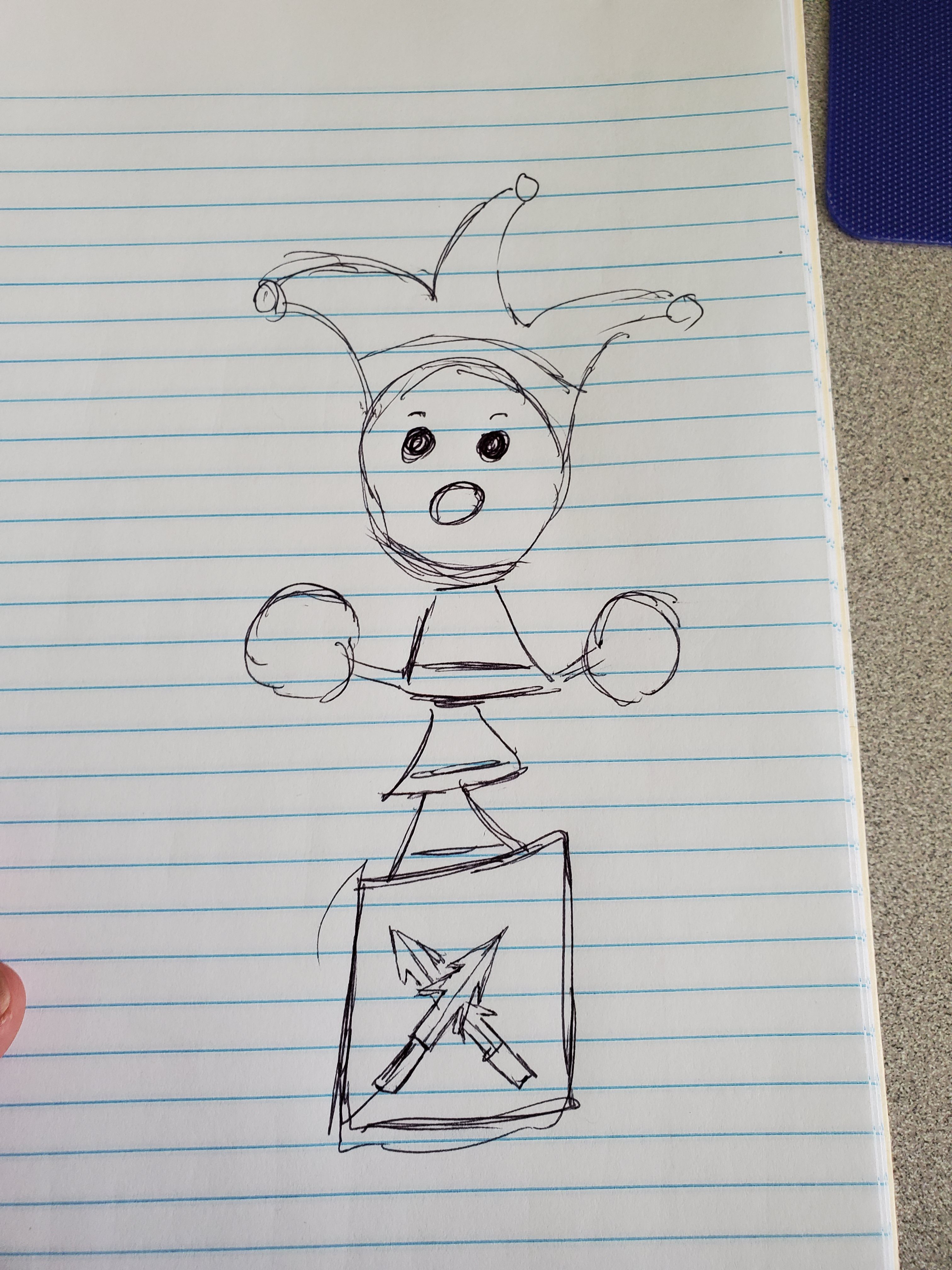
Luckily, without much browsing through Google Images, I was able to find a similar picture.
I think I will repeat this engraving style by making an Illustrator drawing based off of this stock image. Obviously I plan on changing it significantly to express my vision. I think the Jack in the Box is the perfect base point for a logo because thematically I am going with a medieval-fantasy theme and this could be like an evil jester’s puzzle.
Digital Fabrication in the Makery
Since I have stated for a while that I would like to design the container for the puzzle as well (I am taking this project with consideration to be reproduced). I did some quick research on simple box designs using the Glowforge–I really like the wooden aesthetic. I really liked the concept of a “living hinge” (Below) so I incorporated that in my design as well.
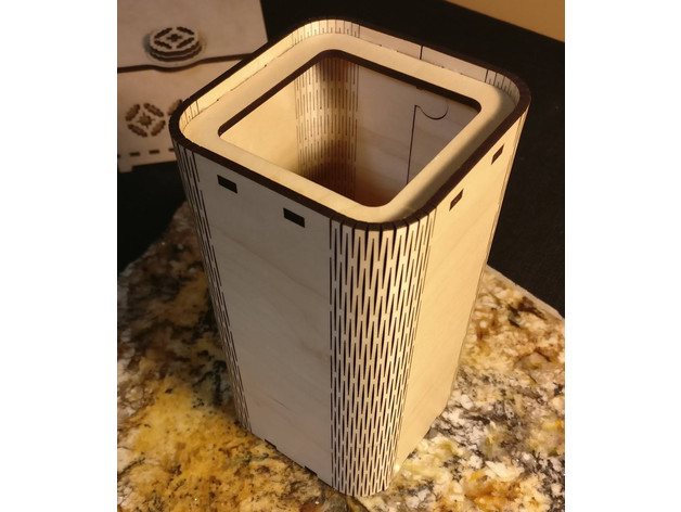
I quickly then generated in illustrator what I thought to be as a box design with rounded corners on the top with a living hinge opening on the side. (Below)
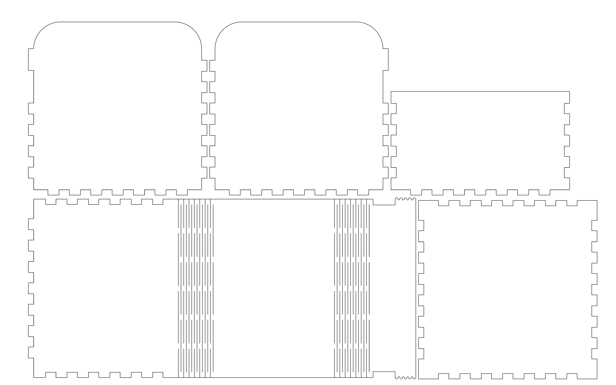
However, one issue that I faced with this design was that I didn’t take into account the thickness of my material that I used. And thus, even though I accurately made the shapes so that my pieces would fit, the thickness of the material prevented my assembly. However, moving forward, this would be a quick fix by extending each of the “slots” by the thickness of the material.