Group Member Roles
Designer: Caitlyn Benjamin
Math Consultant: Kesi Trisadhani
Writer: Catherine Falvey
Project Idea
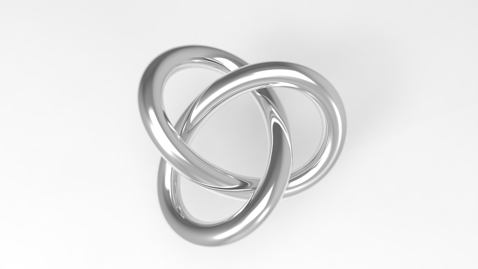
Our group will be making the Trefoil Knot which is one of the prime knots based on chapter 8 of Things to Make And Do In The Fourth Dimension. We were very interested in this particular knot because it looks different with each kind of projection and there are many ways that we can go about designing and finally printing this. If we try to look at the reflection of the trefoil, it becomes a new knot. According to Wikipedia “The trefoil can be obtained by joining together the two loose ends of a common overhand knot, resulting in a knotted loop.” The name itself is derived from the clover – trefoil plant. The trefoil knot is the simplest form of knot, however it is a fundamental part of learning the knot theory. The trefoil knot could have a mirror reflection and although it might seemingly be a mental image only, in the mathematical world these object could be carried out as a real world object.
First Steps
We started out by trying to replicate the unique trefoil design on Tinkercad that is curved, but this turned out to be quite more challenging than we thought. We know that we need to make sure that the knot has three crossings and that it should look like it is made with one single line, like a loop that does not end. We might have to use another platform that will allow us to make better designs. For now, we are also focusing in figuring out how to make a mathematical thought for the trefoil knot. Below is one of our initial designs, however we are sure that there is still plenty of room for improving our knot.

Design Process
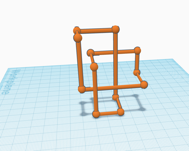
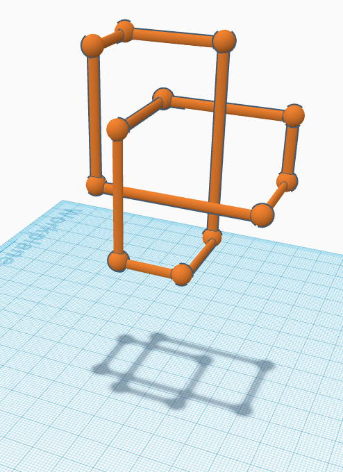
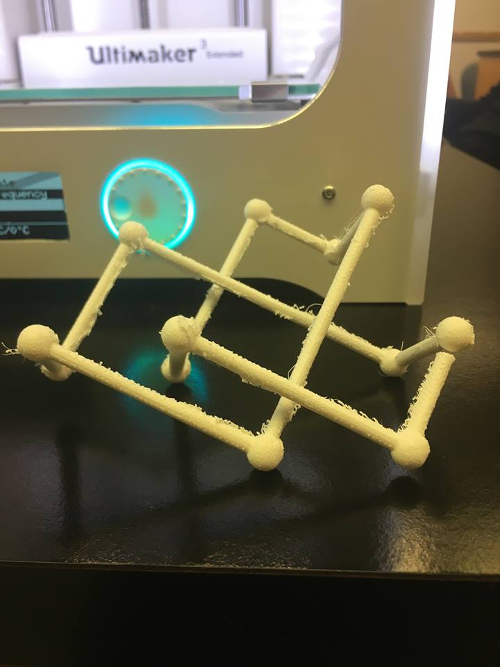
After reviewing our initial design, we realized that a rounded and curved trefoil knot would simply be too difficult to design and print on Tinkercad. We decided to alternate to a trefoil lattice knot, which is made up of lines and connecting points and it also looks rectangular. The rectangular shape was much easier to design because we could put points on tinkercad with spheres and connect them with a cylinder. When you look at the trefoil lattice knot in the beginning, it seems like its just rectangular shapes, however, it could actually be tricky visually. Following along the lines will make one realize that it is actually also a trefoil knot. The process itself was long and tedious, but it came out great! Our first print of the Trefoil Lattice Knot had a 20% infill and we added supports to keep the thin bars from collapsing.
Trefoil Lattice Knot
One thing that we could study from the trefoil knot is the shadow produced when we lift the object up in the air. After consulting with Professor Taalman, we noticed that we could also make the trefoil knot shadow after printing the actual physical object.
The Shadow of the lattice knot appears when we lift the object up in the air, it shows a different shadow when we rotate it by 90 degrees.
This is something that we can do with the different kind of trefoil knot, including the original one, like the one shown below.
Final Prints of the Trefoil Knots
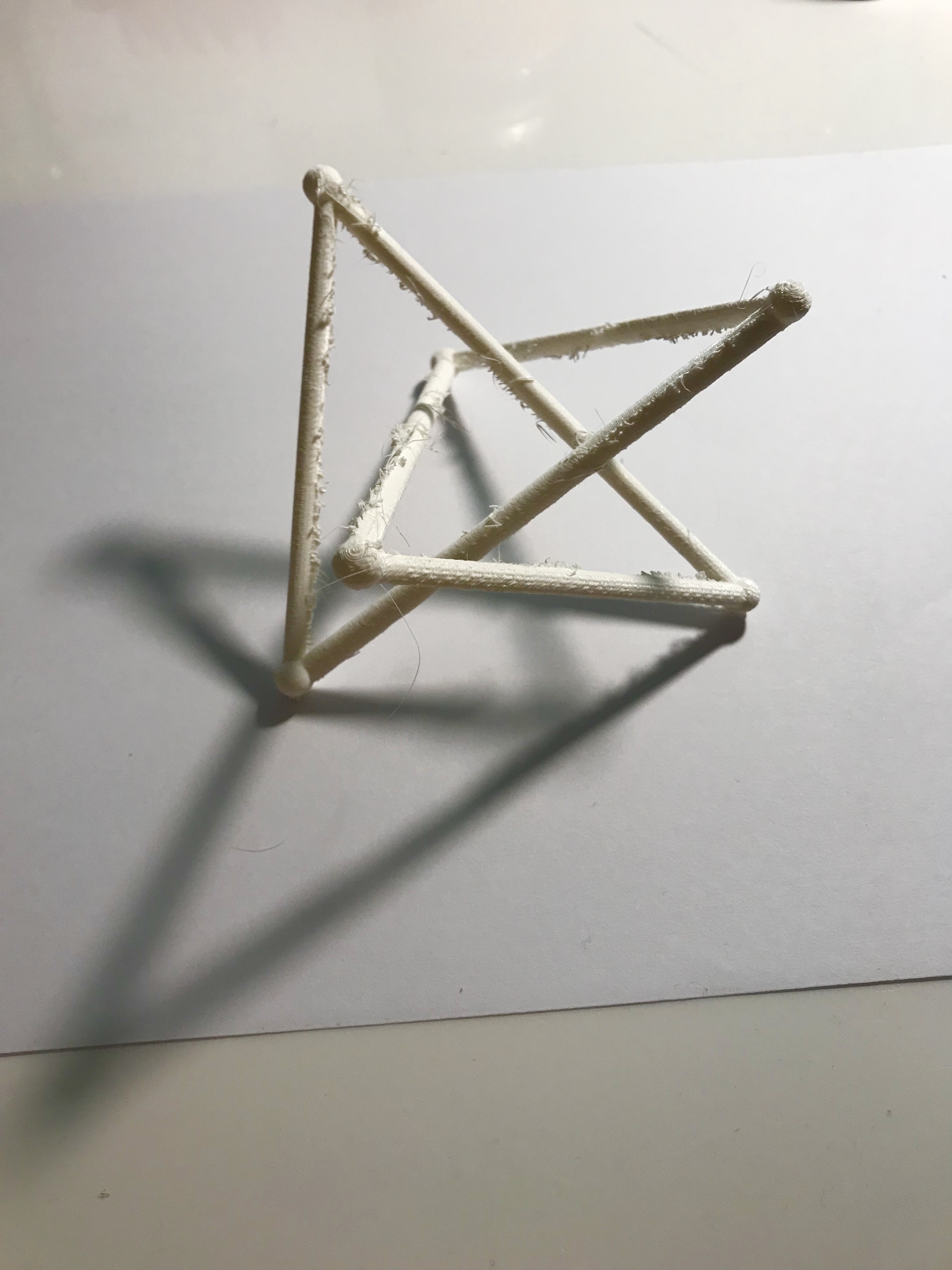
After many trials and tribulations, we finally got the lattice trefoil knot to print on the Ultimaker. We used a 50% infill and generated supports to keep the bars from collapsing in on the hollow object. We also decided to design another stick trefoil knot (triangular shaped knot, as opposed to the rectangular lattice trefoil) and attempt to print that on another Ultimaker in the classroom.
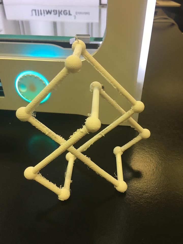
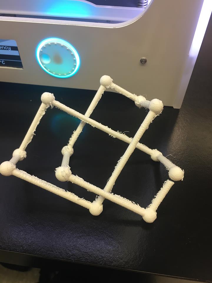
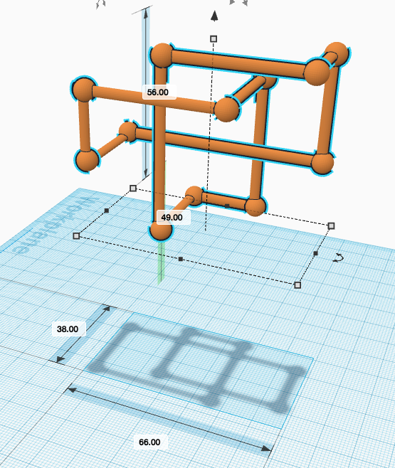
We also added another design to print out. It is also a lattice trefoil knot, but this time it has a rectangular shape. We see how deforming the original trefoil knot a certain way can result in a different kind of trefoil knot. For this trefoil knot, we used coordinates on Tinkercad so that we could also put spheres at a point and then finally connecting them with cylinders. The coordinates we used to design the triangular lattice knot is shown below:
p1=[s*0.300775, s*1.301248, s*(-0.702434)];
p2=[s*(-0.976281), s*(-0.910795), s*0.701983];
p3=[s*0.976171, s*(-0.910795), s*(-0.702076)];
p4=[s*(-0.300495), s*1.300967, s*0.702620];
p5=[s*(-1.276451), s*(-0.390204), s*(-0.702474)];
p6=[s*1.276282, s*(-0.390420), s*0.702381];
Our second lattice trefoil knot printed beautifully the first time, once again using a 50% infill and supports. Though the Ultimaker has caused our prints to be somewhat “thready” looking, we are very pleased with the outcome. The trial and error we went through with our first lattice trefoil knot really helped us print this one successfully on the first try.
The Mathematics of the Trefoil Knot
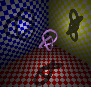
As shown in the picture below, we got a shadow after lifting our design up in the air on Tinkercad. This shadow projection is very important because we were able to find out that the object will be able to give us a different shadow when we rotate the object a certain degrees, that is if the point of the light stays the same. Another way to look at it is also if we keep the object still, we could change the point of the light and see the shadow projection of the trefoil knot.
The only thing that we cannot determine on Tinkercad shadow is which line goes over or under. By drawing the shadow manually with our design, we will be able to trace the lines and make sure to know which line goes over and under by creating a little gap in between the intersections.
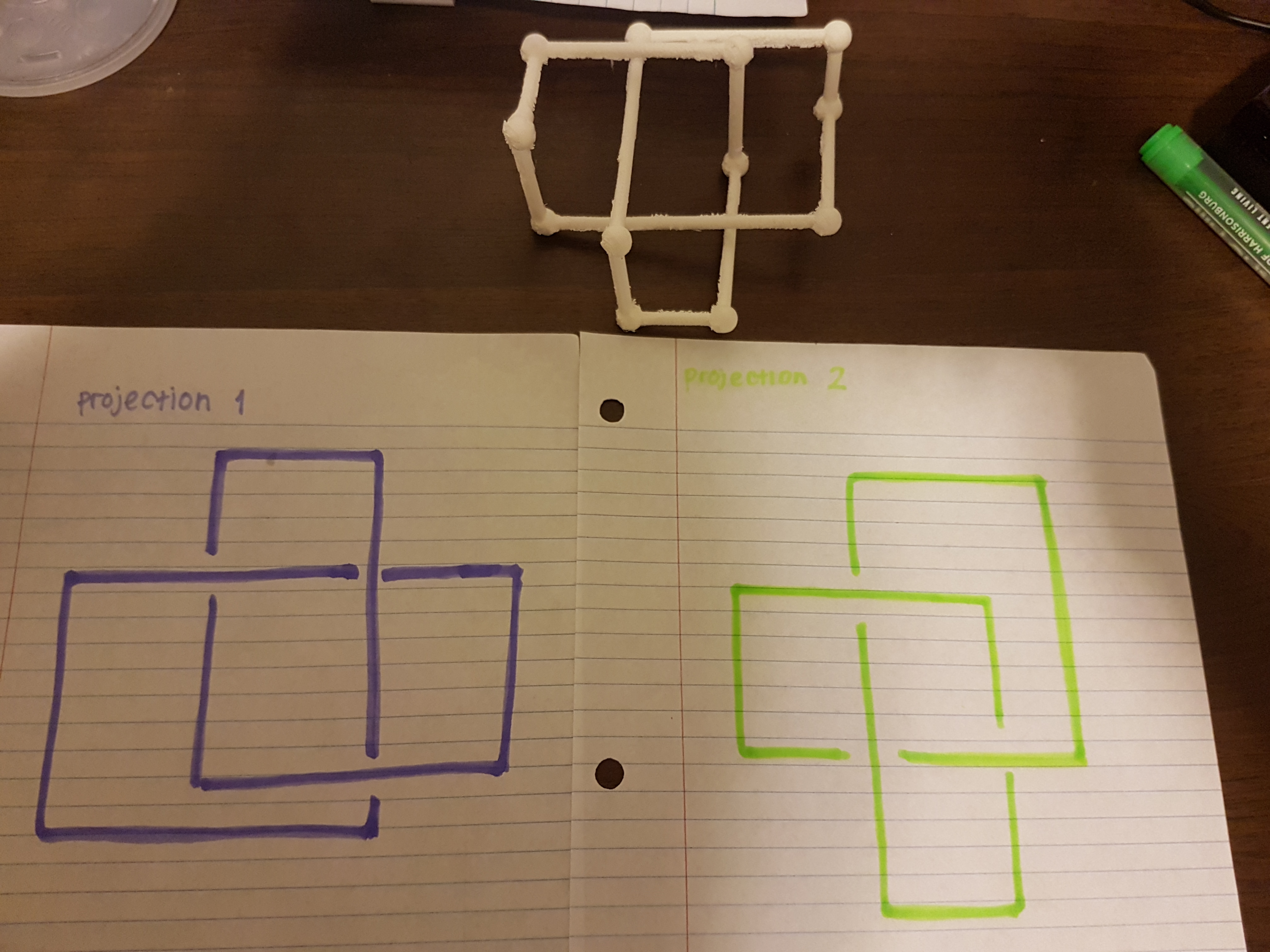
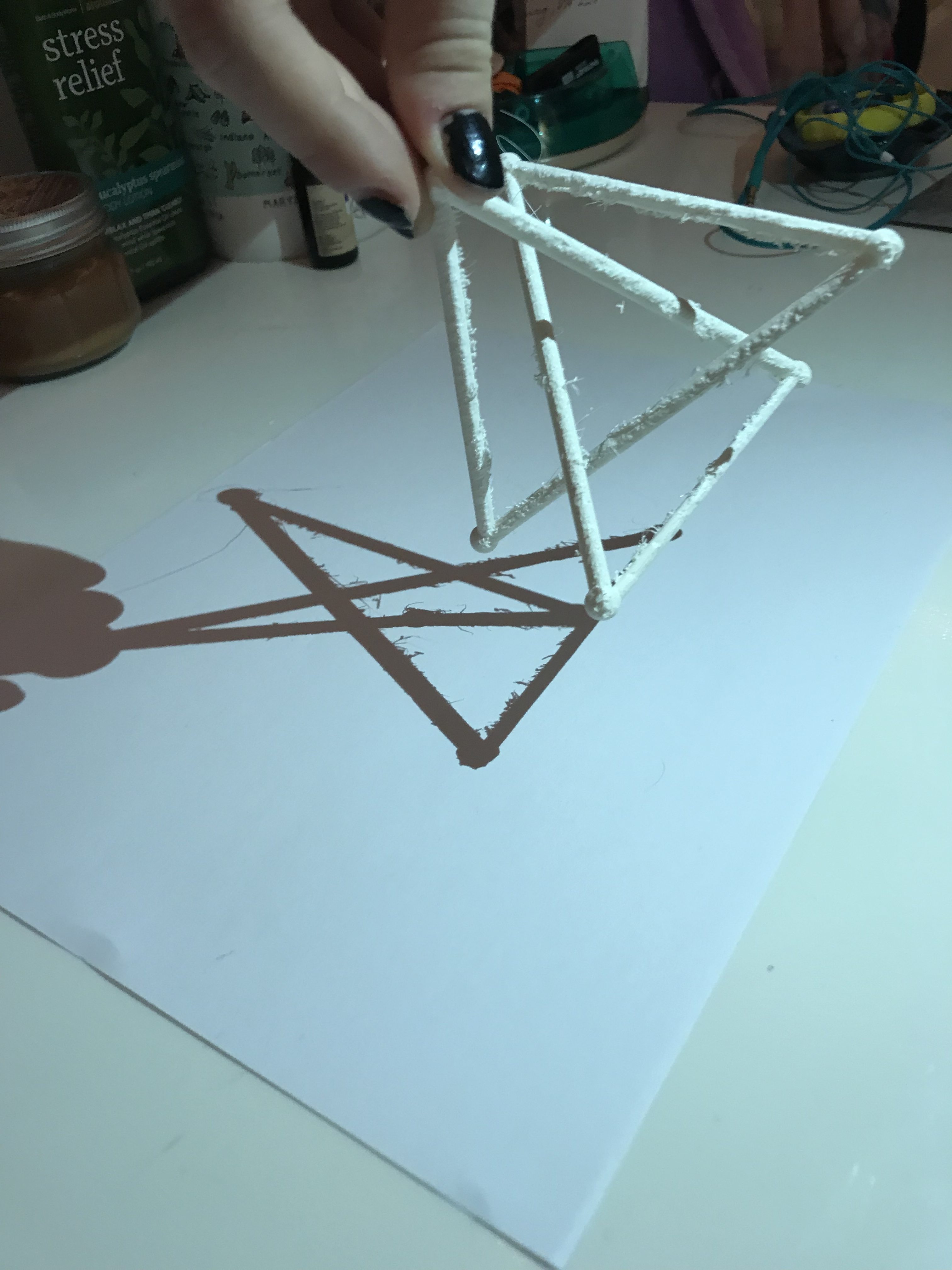
One of the most interesting facts about trefoil knots is that when we create the physical print, we are able to create different projections from it based on its actual shadow. As demonstrated by the picture below, this is how we obtain the different projections. We put a flashlight right on top of the object, therefore creating the intricate shadow. If we rotate and change the angle of our knot, then it will give out a different shadow every single time.
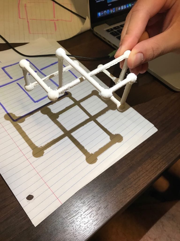
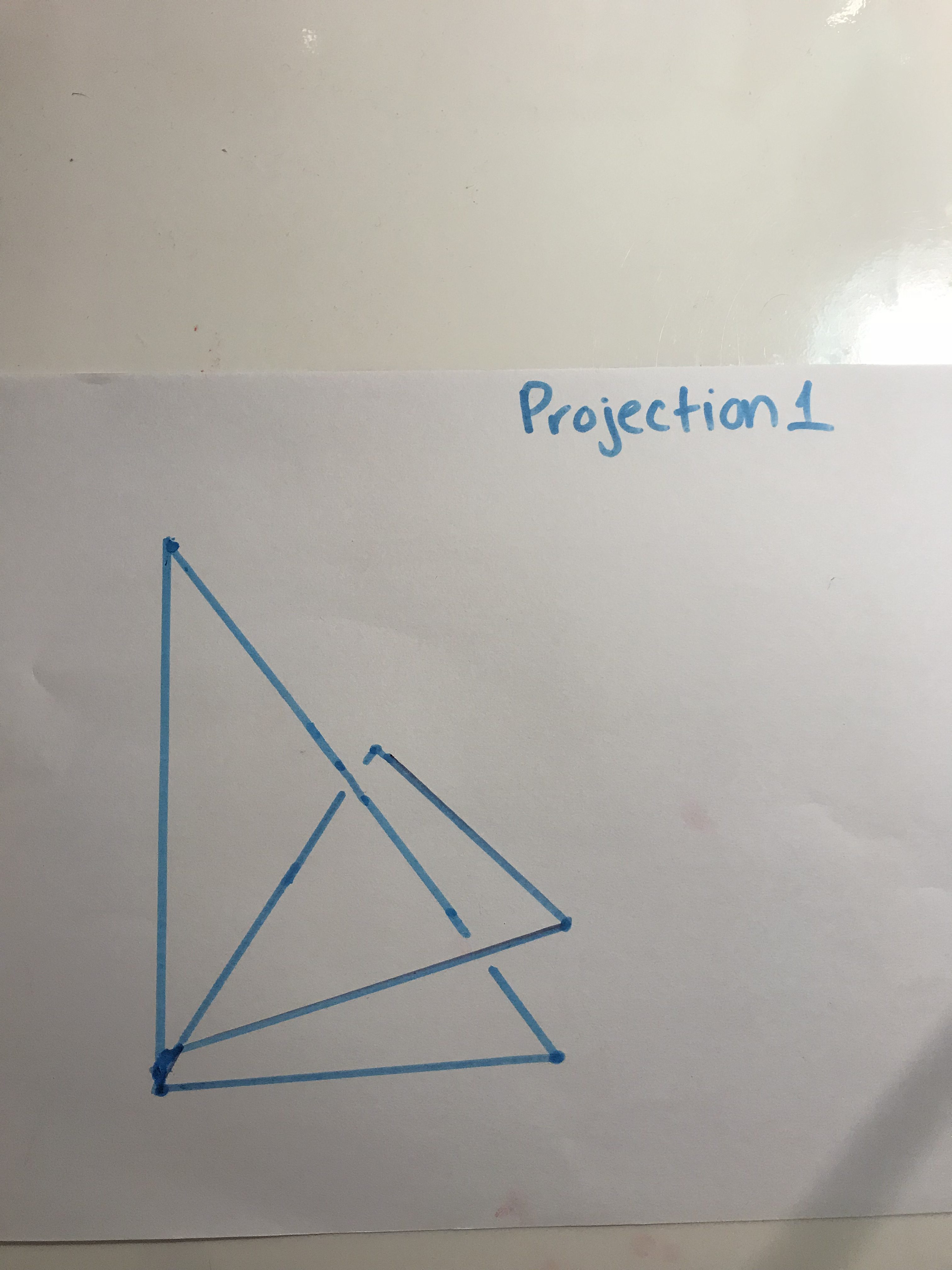
Below is an example of one of the traced projection. When the lines are disconnected in the intersections, it means that the structure (the line of the cylinder is below another one). We traced it that way in order to know that one line is above or below the other.
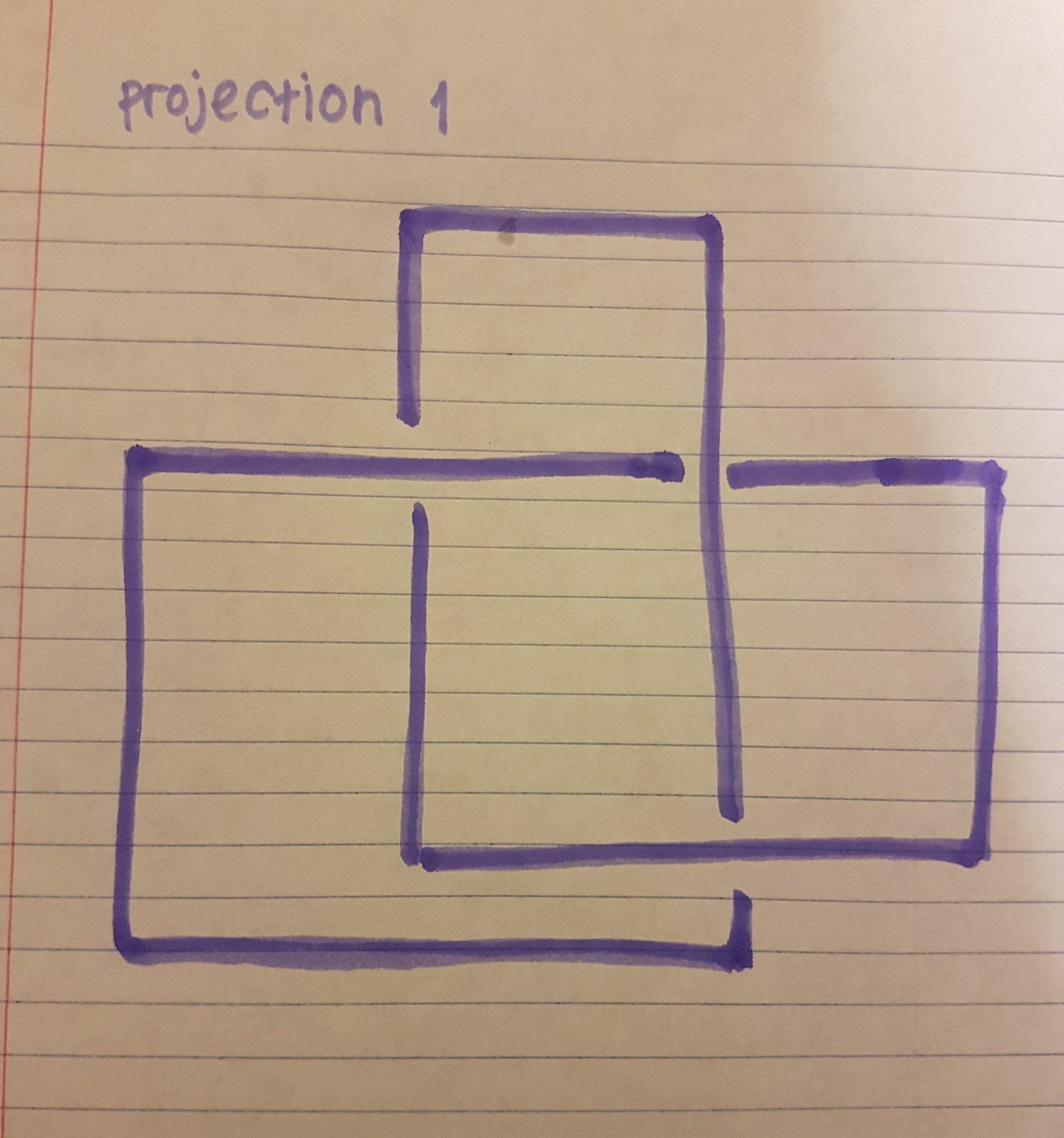
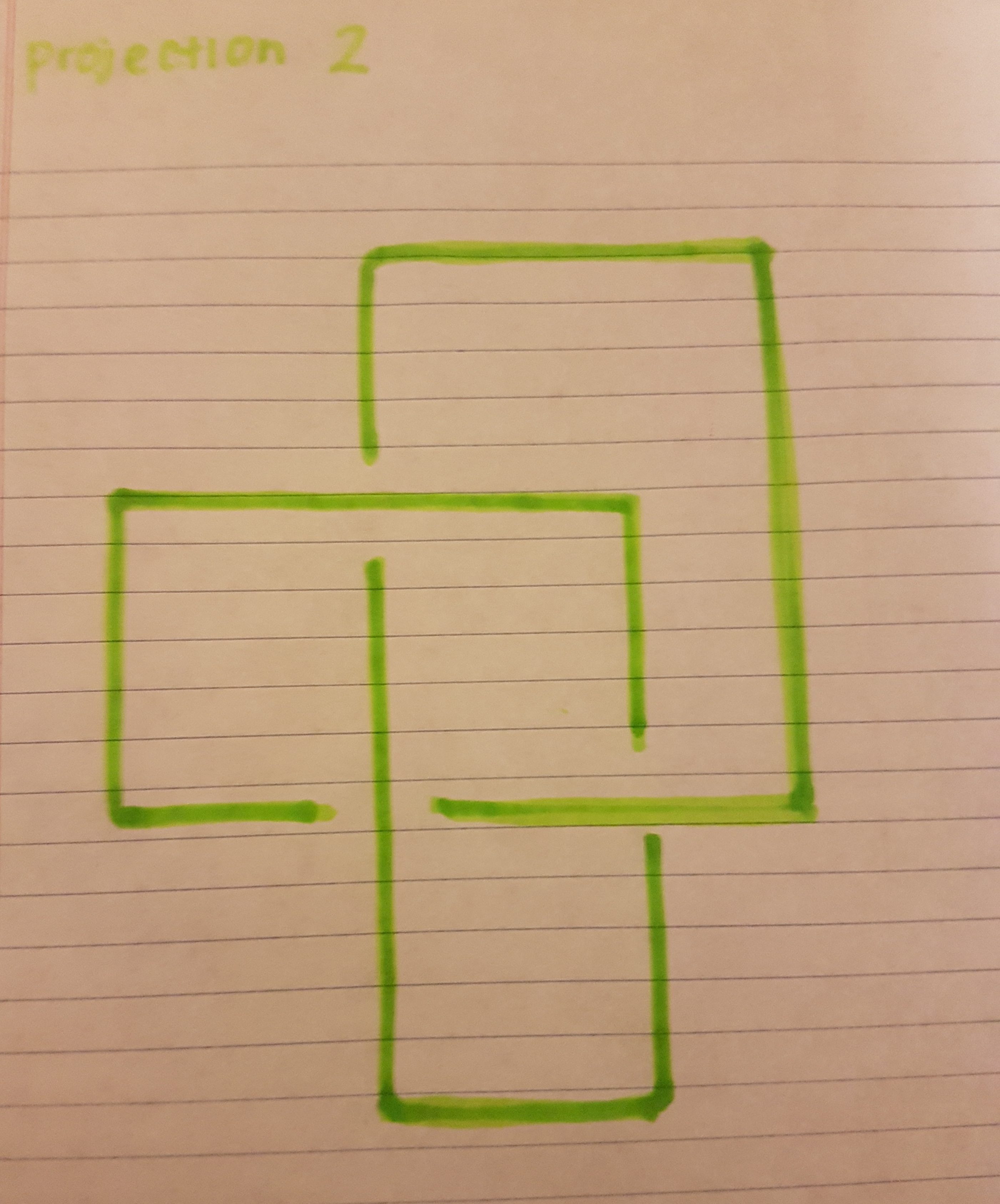
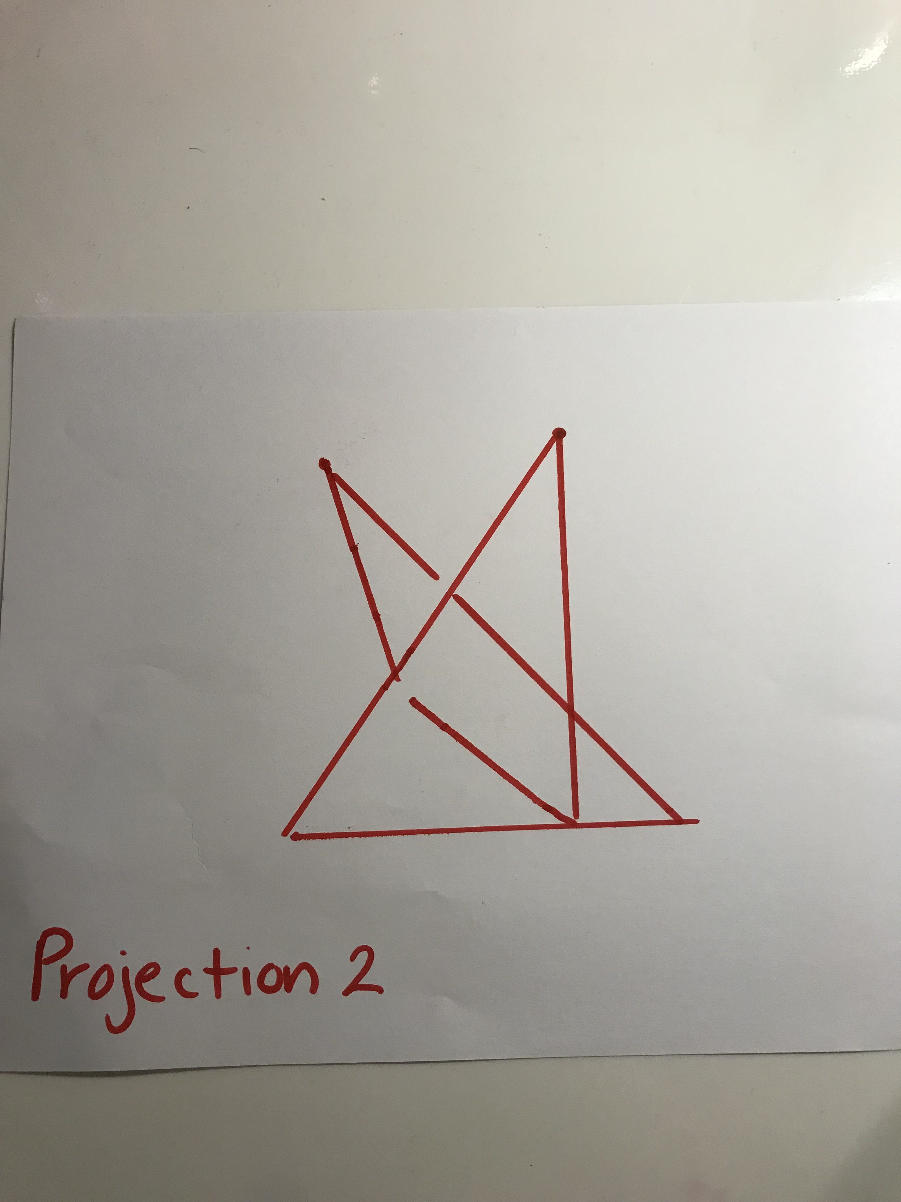
Below is an example of the second projection that we made after rotating it exactly 90 degrees. Same thing with the first projection, we basically traced the line created by the shadow and making sure we know which line is below or above each other when they intersect.
We also printed another interesting model of the lattice trefoil knot in which we used the same techniques to get different projections, pictured here.
Like the other lattice trefoil knot when the model is raised and has light shining on it we can get observe unique shadow projections.
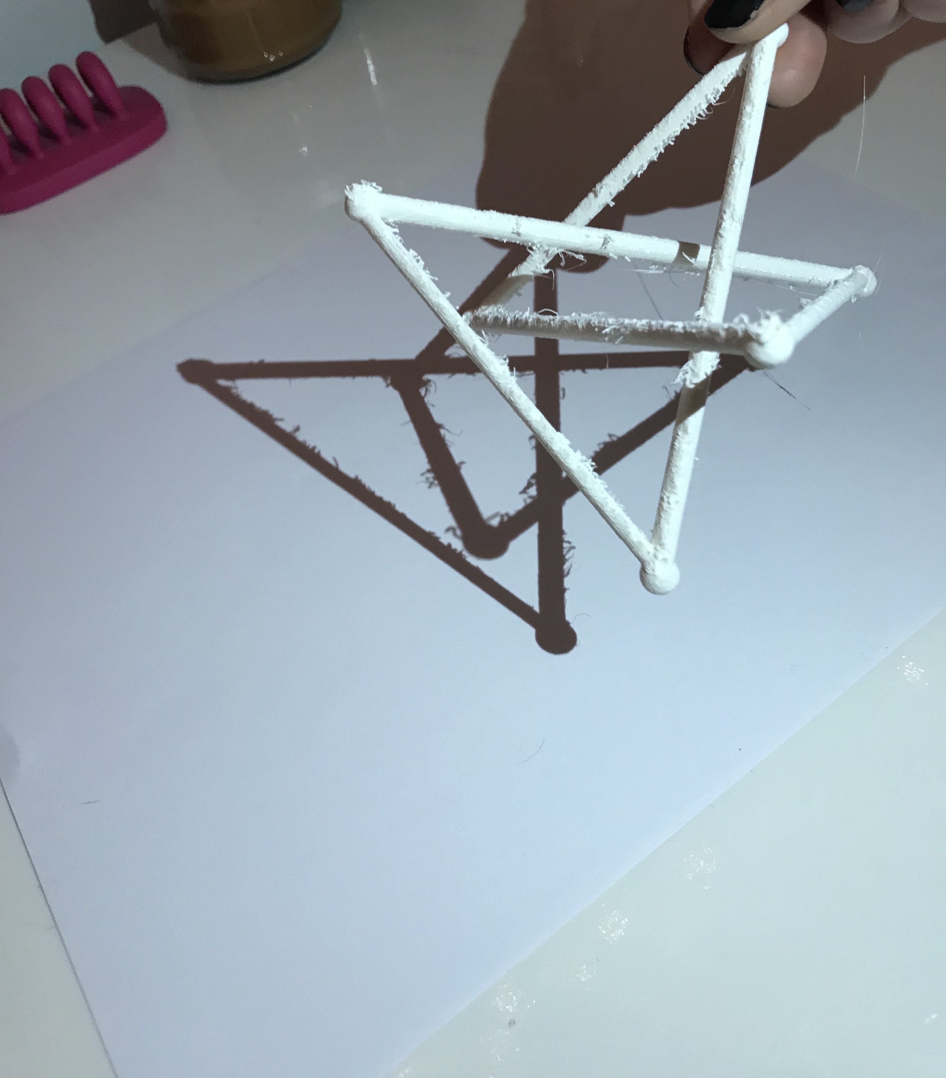
When we turned it 90 degrees and tilted the model we were able to see a completely different, unique shadow for the second projection. A simple tilt of the angle of the light source or the trefoil knot can alter the look of the shadow and create more neat designs.
From this project, we are able to understand that there may many more possibilities of projections by one single lattice knot print. As we know, there are different kinds of trefoil knot. We are sure that those other trefoil knots are able to also create projections that will be unique from the different angle that it is shown. We are very amazed by how a simple knot like the trefoil knot is able to give out these different projections.
Make the Model
Thingiverse Links: