Hello
Hi, my name is Austin. Computer Science is my major with a minor in both Mathematics and Computer Information Systems. I also am a Teacher Assistant for Computer Science. During my free time, I will most likely be lifting at UREC, playing intramural sports, or taking a nap. You will probably see me getting cookout sometime late at night.
I currently have no experience in 3d printing. My friend took the course last semester and made me a little gingerbread house though. I am taking this course because the only general education credit I need left to graduate is a lab. I really should have taken a lab when I took physics or geology. My goal for this semester is to design something cool and give people random stuff I print.
Check out my designs on Thingiverse: @austinjlam
Thingiverse Model
Playing Card Box by SometimesCake
https://www.thingiverse.com/thing:38001
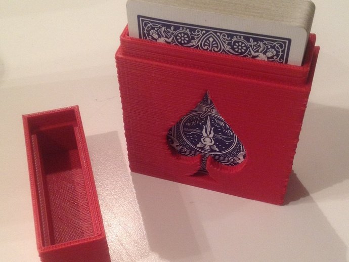
I chose this model because it can hold a deck of cards. I am a big cards guy from poker and blackjack to a typical house game. I always have a decks of cards lying around and no where to store them. This box will allow me to keep each card together while looking nice with the spade on the side.
Thingiverse Print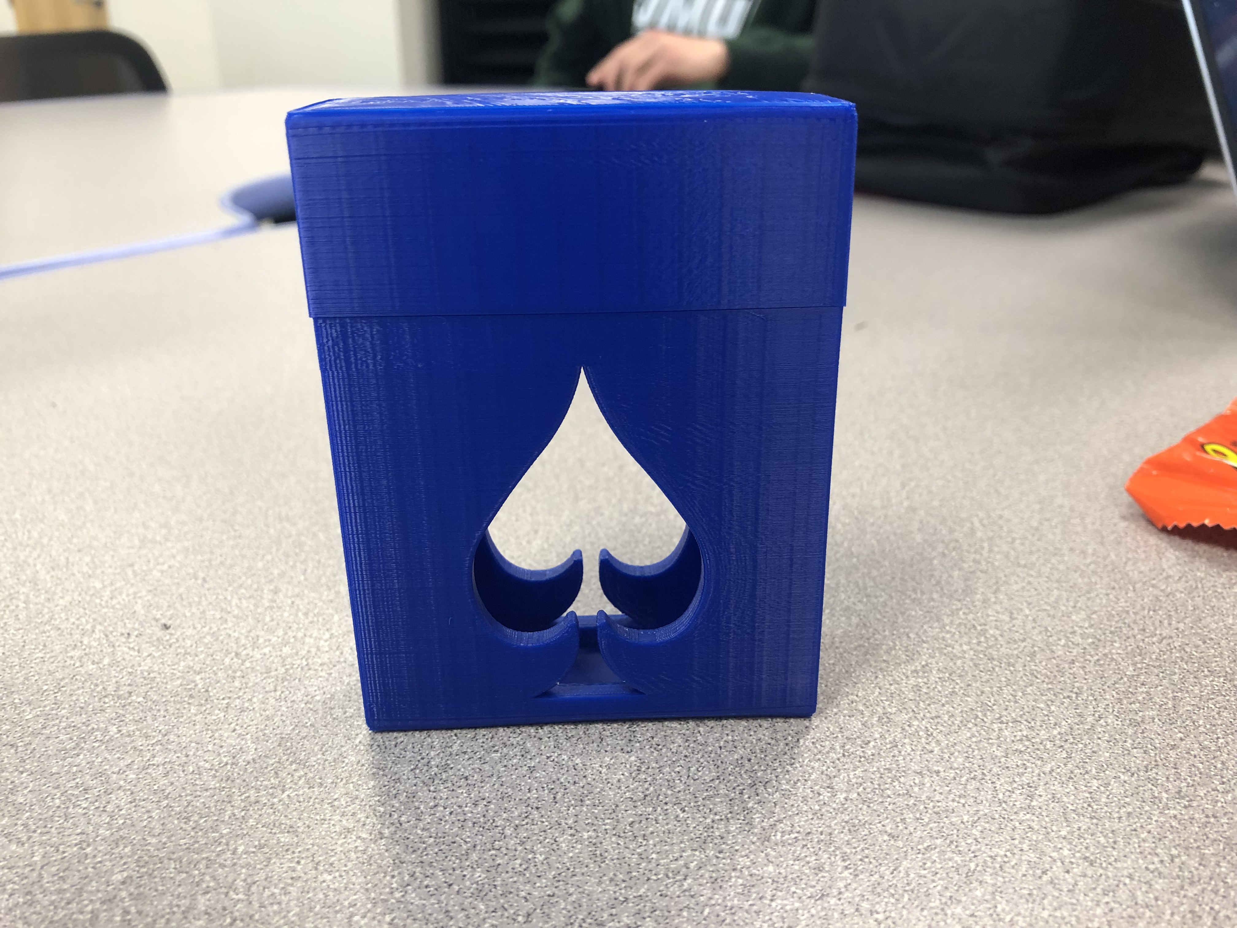
This 3D print of the card box was a success in my opinion. The lid of the box fits over the bottom, the design of the spade came out great, and it feels strongly made.
https://www.thingiverse.com/make:628648
20 Forms in Tinkercad
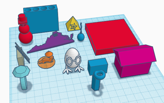
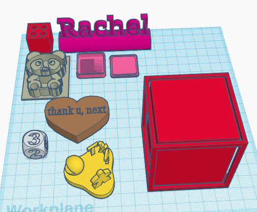
- I made a pencil holder that holds 4 pencils smaller than 7mm wide. I used a solid box and a cylinder as a hole. I used Ctrl-D to duplicate the same hole 3 more times and shifted them with the arrow keys (snap grid 1mm) so that they are 2mm apart.
- I made a name tag for my friend Rachel that says Rachel. I used a round roof as a platform and placed a text above it. I used the ruler to align them together.
- I made a heart with an imprint of text inside rather than on the outside by making the text a hole. I used the alignment tool to level the top of the text on the heart.
- I made a panda from saving an image of a panda from google, converting it into a svg, and importing it into tinkercad.
- I made a die and put the numbers 1-6 on it by adjusting the workplane and putting the numbers in as holes.
- I imported a STL file of a rounded box from https://www.thingiverse.com/thing:3499293
- I made a random flower platform with 3 curves and put shapes on each edge and grouped them together.
- I made a box that can hold a small picture on 4 sides. The center has JMU indented into the top. I did this by having a solid box as an outer shell, a smaller box inside that’s a hole, and an even smaller box that is solid. I then made 4 small boxes for the outer shelled box so the pictures placed inside will be visible.
- I used a shape for Virginia and grouped it with a house located where I live.
- I made a box with another box inside that is a hole so something can go inside.
- I made a snowman. I combined 3 spheres, a cone, and made a hat from a box and 2 cylinders where one of them is a hole to make the hat hollow.
- I imported a ladder svg from https://www.thingiverse.com/thing:2441381 and adjusted the rotation so that it leans against a wall.
- I made a pyramid with 2 stars on opposite sides. I first created one of the stars and then made a duplicate and flipped it to get the same angle but for the other side.
- I made a battery holder that holds 4 AAA batteries. I duplicated a battery shape from components and aligned them apart by shifting each one 12mm from the one beside it. I grouped 4 batteries together and made them a hole for a solid box.
- I made a balloon by adjusting a sphere to be more oval like. Flipping a cone to lie the tip against the balloon as an air opening. I then used the scribble tool to draw my own string that I connect to the cone.
- I made a ring with a diamond on top. I aligned them together and raised the diamond above the ring.
- I imported a lego block in stl from https://www.thingiverse.com/thing:1729056 and connected it to the bottom of a house so that someone can connect it to their lego set.
- I imported an otter from google and using a convertor to make it a svg. I then gave it a little umbrella for when it gets hot outside by combining a cylinder and two cones, one of which is a hole to make the underside of the umbrella.
- I made a chicken sort of. It is an egg with 2 chicken legs aligned with each other. I then put glasses on the egg which is the chicken’s head or body or both.
- I made a basketball hoop using a solid cylinder with a hole cylinder inside of it to make it hollow. I then added a backboard using a solid rectangle and a rim with a torus. I grouped all the shapes together.
Tinkercad Print

Of the 20 items I had designed in Tinkercad previously, I printed out the 4 sided picture box and added the JMU logo on top. I had first decided I wanted to print one of the more simpler items of the 20 and attempted to print a thin hollow box with one of the small edges missing so that the box is open. Unfortunately the print failed twice only printing the base of the box and I am not sure why. Possibly because the box is too thin? My next option was to print this picture box which is shown in the picture above. After many hours, the print finally finished and it came out pretty good. There is a problem however with the frame that goes horizontally across the top on all sides. It seems that they needed more support during the printing process because there are strands hanging down into the opening.
Summary of Group Tinkercad Project
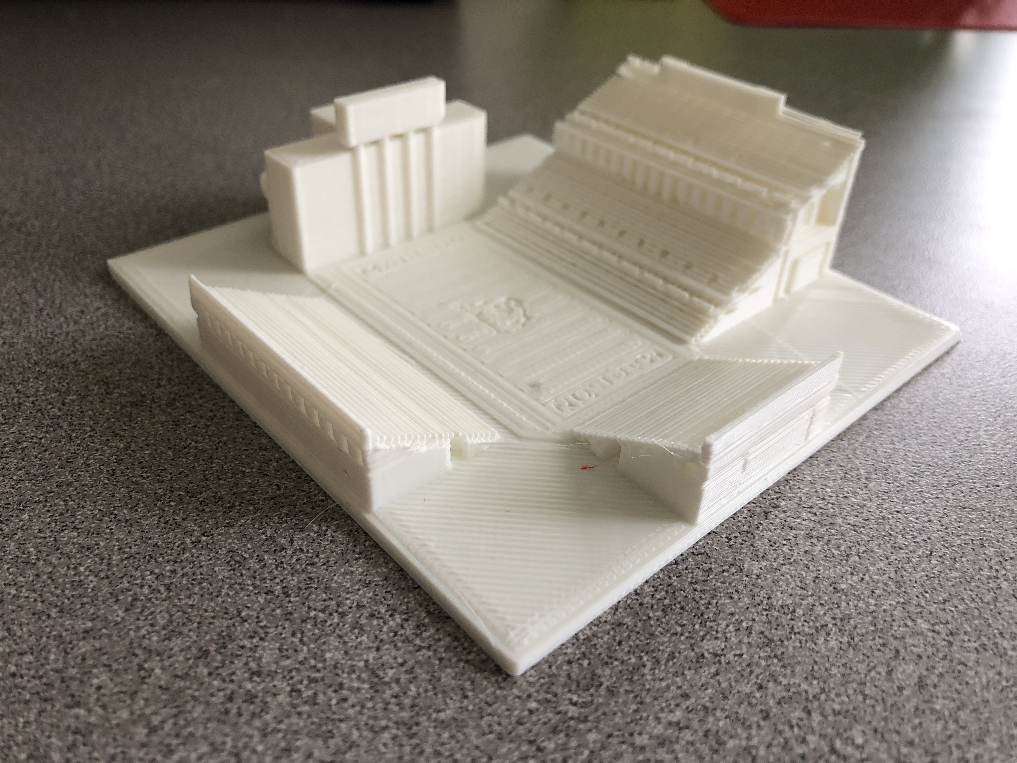
Bridgeforth Stadium (with Ashley Boylan)
https://www.thingiverse.com/thing:3519606
For this project we created a model of JMU’s Bridgeforth Football Stadium. We did this by first designing the football field which includes the 10 yard markers, Madison touchdowns, and the JMU Duke Dog logo which I imported as a SVG. We then moved onto creating the scoreboard and then the bleachers which was the most difficult and took a lot of time. To make the bleachers, I designed each layer individually which included rectangles for bleachers, supported by cylinders, on top of a rectangular platform. This was more difficult than expected because each bleacher had to be spaced out to allow for stairs and/or walkways to exit the stands. Then I had to duplicate each layer and align them above the previous layers and alter the bleacher lengths if needed. The design printed out better than I expected but does not perfectly represent the design we had created in tinkercad. This is probably due to the level of detail and small size at which we printed the stadium out. The stairs/walkways were 1mm wide in tinkercad which does not appear in our 3d print at all and the designs on the field came out a little deformed. Also we had to use support for all the overhangs which was difficult to remove, as it was so compact, without breaking the fragile bleachers.
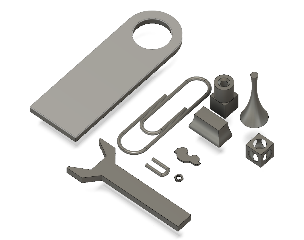
20 Forms in Fusion 360
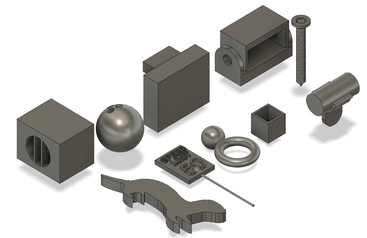
- I created a penny trap. I started by creating a box and a sphere. I then moved the sphere to be centered with the box and then combined the two where the sphere was a cut.
- I created a spin-able, curved like dreidel thing. I did this by sketching a 2d figure from lines and using the revolve tool around the vertical edge.
- I created a screw by sketching a line. Turned the line into a pipe and added threading. I sketched a triangle at the bottom of the pipe. I revolved the triangle around the y-axis to make a point for the bottom of the screw. I sketched and created a cylinder at the top of the screw. I sketched a plus sign and cut it out of the top of the screw.
- I created a nut. I sketched a polygon and extruded it. I sketched a circle in the center of the polygon and extruded that as well. I combined the two and made the cylinder a hole. I added a thread to the inner cylinder and modeled to get the actual threading to appear.
- I created a box with a cylinder on top and through both the objects is a countersink hole aligned in the center.
- I created a paperclip by using the sketch tool to draw lines that follow the spiral of the clip. I used the fillet in sketch at the sharp corners to make the curves of the paper clip. I sketched a circle at the outer start of the paper clip line. I used the sweep tool to sweep a pipe from the circle through the path of the sketch.
- I created the bottom half of a pipe clamp by starting out with making a cylinder as a pipe. I then viewed it from the top view to see the face of the cylinder and created a new component. This component is the bottom half of the clamp. I made a center circle the size of the face of the cylinder and made another circle around that one with an offset. I then create two smaller circles, one on each side, the radius of the offset circle and the center circle. I then extruded this new component, with symmetry, to make it a 3d object. I created the clip or bottom of the clamp by adding a new construct and pulled the bottom plane down. I sketched a center rectangle and extruded the extent to an object (the clamp) so that it connects to the clamp.
- I created a curved bar from sketching an initial rectangle. I constructed an offset plane from that rectangle that I then sketched a smaller rectangle on. I then lofted the two rectangle sketches together and changed the direction of the profiles.
- I created a key chain plate by sketching a rectangle and using the fillet tool to curve one of the edges. I sketched a circle and aligned it to the curve with the concentric constraint within the previous rectangle. I extruded the outer shape of the circle to make the plate.
- I created a car by sketching two copies of the same circle, placing them on a line, making arches, and extruding all of them.
- I created a rink by combining a torus and a sphere, aligning them together, and combining them.
- I created a hexagon bold wrench by sketching a rectangle with lines. I then cut out the bold holder by sketching a hexagon and using the midpoint constraint to line the center of the hexagon to the flat edge of the head of the wrench created by lines. I then extruded the sketch to make it 3d.
- I created a box that can hold stuff. I did this by creating two box shapes. I aligned them and combined them with a cut.
- I created a speed limit sign. I sketched a line and turned it into a pipe. I sketched a rectangle and extruded it symmetrically. I sketched text and extruded them as well. I placed the text above the sign and joined them together.
- I created an otter by importing a svg file that I converted from a google png.
- I created a bowling ball by making a sphere. I then created 3 holes in the sphere and made them small for finger placements.
- I created a wall with a shelf by starting with a rectangle for the wall. Constructed a new horizontal plane that I raised. I then created another rectangle for the shelf on that new plane.
- I created a box with a hole that is separated by two lines. I did this by first making a box. I inserted a hole partially through one end. I sketched two lines at the opening of the hole. I then used the web tool to add the separations in the hole.
- I created a straight edge U pipe by sketching 2 straight lines connected by a curve one. Then I converted the sketch to a 1 inch pipe using the pipe tool.
- I created a pivoting 3-sided outer box that rotate around a component that holds it. I did this my making a base that contains two supports on both sides with holes. I then created a 3-sided outer box that I also added holes to. I used the joint tool between the holes to align the two together and can pivot.
Fusion 360 Print
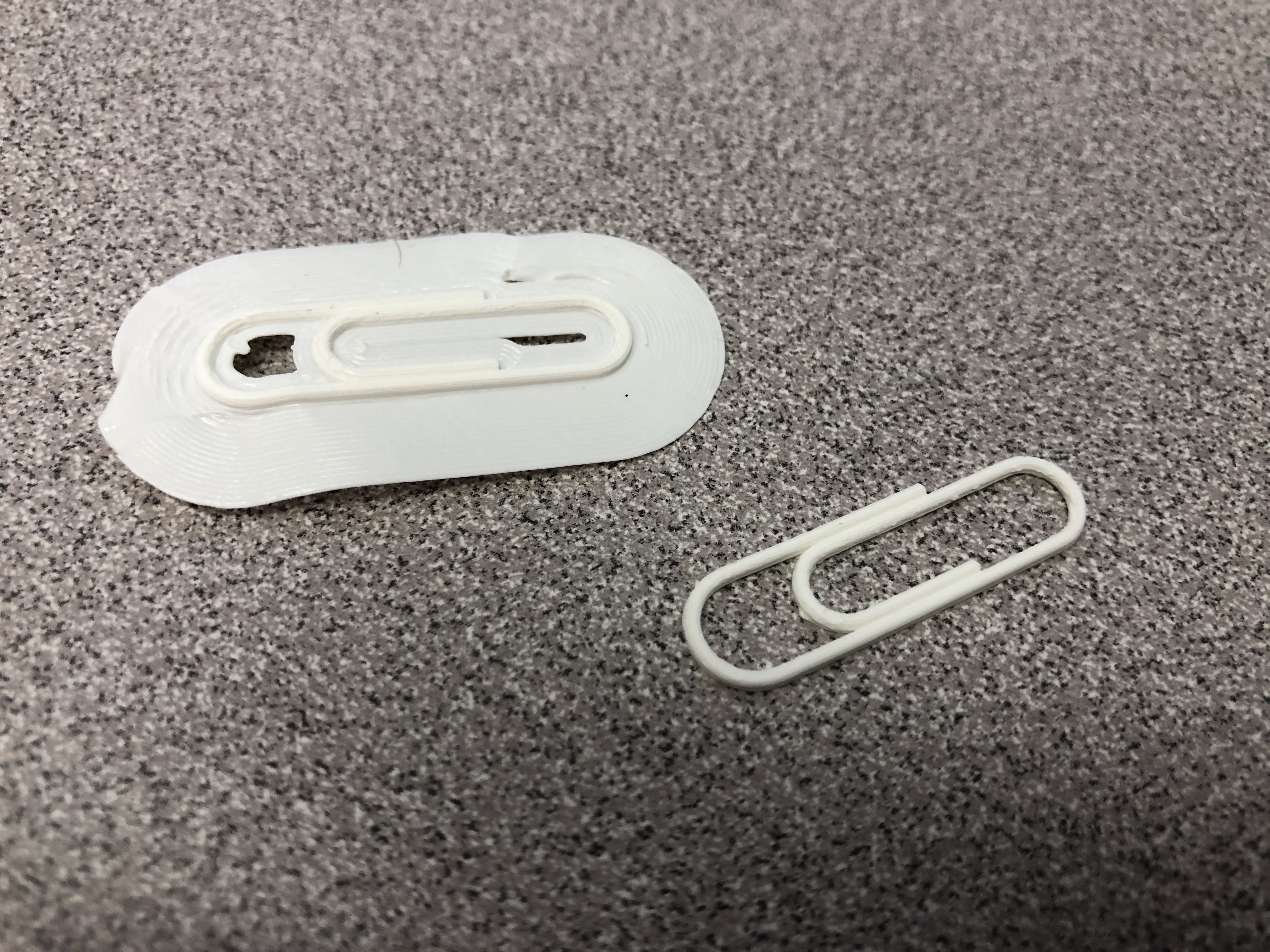 I printed a paper clip from fusion360. The first attempt on the left was a fail because I had printed it with a plate adhesion and I was not able to remove it from the clip. I then reprinted it again without the plate adhesion and the paper clip came out exactly as I had designed.
Fusion 360 Vase Design
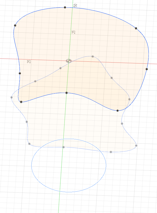
I created this design by first sketching a circle to act as the base of the vase. I constructed a new offset plan in the x-z plane, which lays horizontally, and raised it above the the circle. Using this plane, I sketched own spline, different than the design of the video, using my own points. I repeated the same steps, creating a new offset plane and another spline, with a different height and shape. With my 3 sketches in different dimensions, I used the loft tool to combine them and create the shape of the vase. I finally added a larger twist to my vase to make it more unique. I had tried to use a guard rail to make the vase cooler, as explained in the video, but I did not quite understand how to get the rails to match/connect with the splines.
Fusion 360 Vase Prints
[^ small demo print]
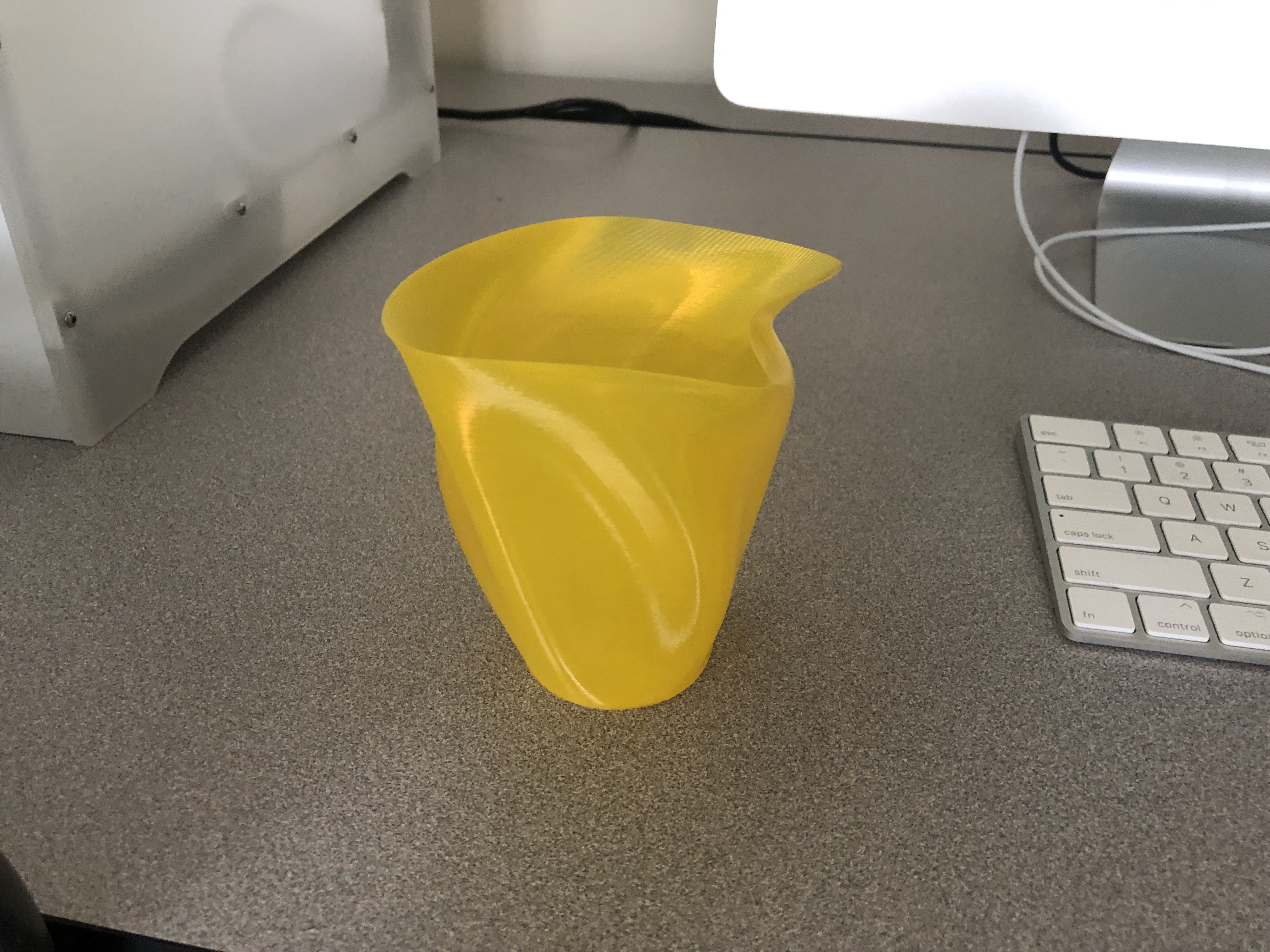
[^ large fianl print]
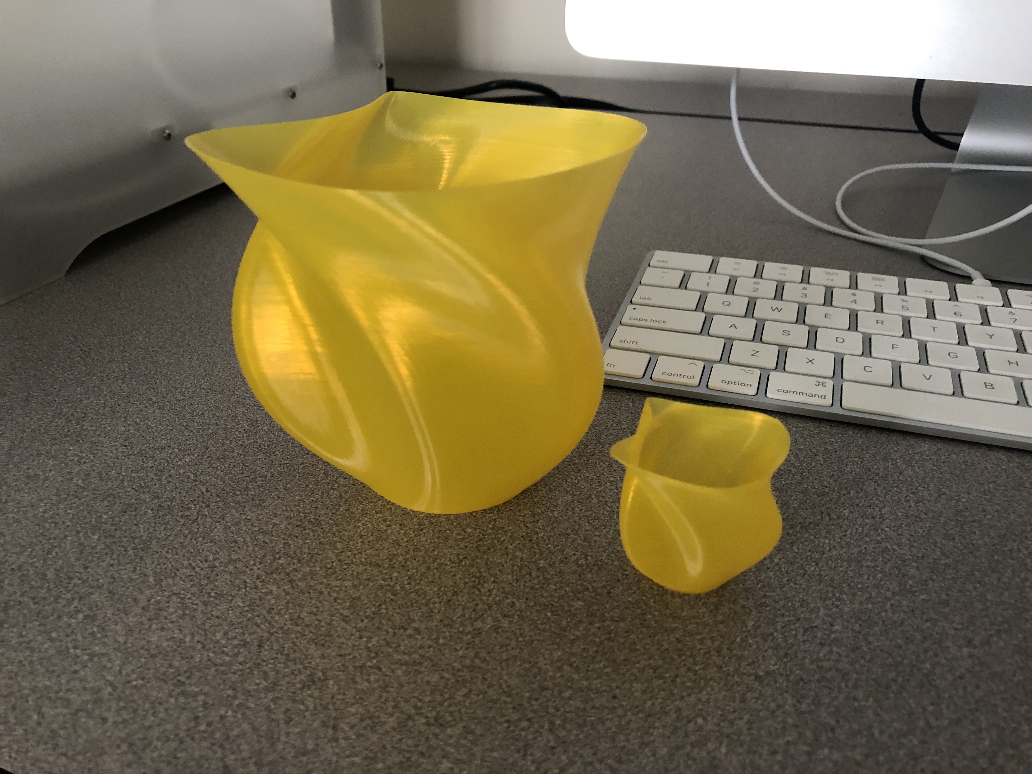
[^ large and small print]
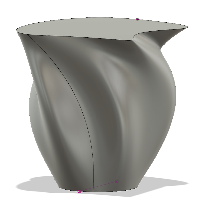
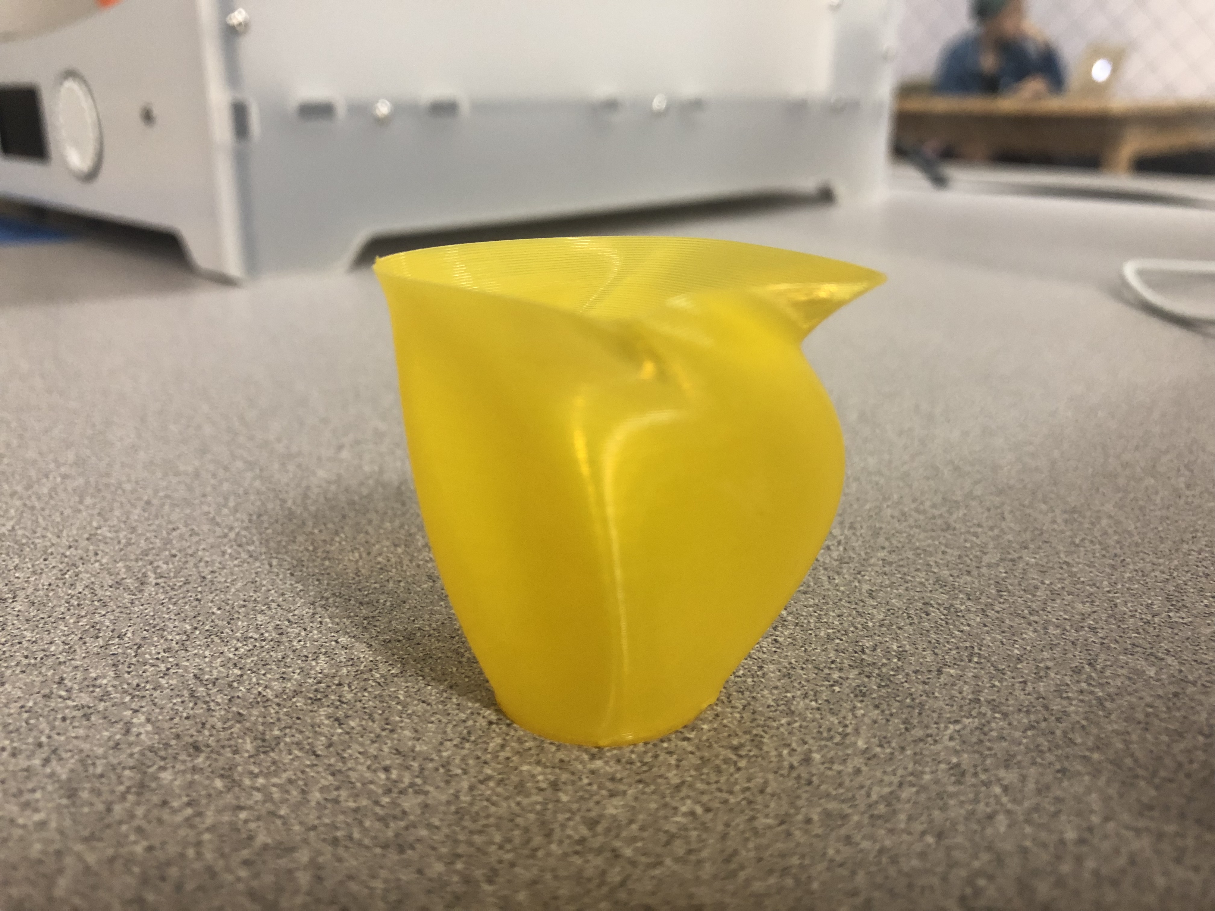
The vases both came out as a success. It looks exactly like what I had designed and there are no flaws in the print where the print came out flakey or has any loose ends. I was worried when I imported the stl into candid because candid had highlighted the overhang at the top of the vase with red, in which I would assume would be a warning. However, I went ahead and printed it as is for the small demo design and it came out great and so I continued with the large one, without changing anything, and that came out great too.
https://www.thingiverse.com/thing:3552050
20 Forms in OpenSCAD
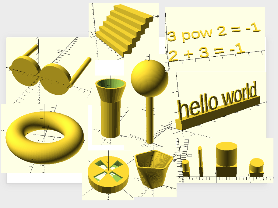
- I created a bowl. I did this by copying the code from Professor Taalman’s video https://www.youtube.com/watch?v=kn1aqnHF1RE. However, this bowl was made by having a method called polyshape that takes in a parameter to either make a solid shape or hollow shape. This method is called 3 times. It is called as a solid and extruded for the base. Then it is called again after being translated but passed in “no” for solid that makes the body of the bowl. Finally, it is called for the rim of the bowl after being translated by the base height and body height.
- I created a flash light. I did this by making a cylinder. The height of the handle for the flashlight is the base variable. All other variables/dimensions of the flashlight change according to the one height. I did this by declaring all the variables at the top of my code and using the variable names when implementing the shapes. For the shapes, I create a cylinder for the handle. I then create a method for the headlight that takes the difference of two cylinders to make the open end of the flashlight where a light bulb is normally found. The head of the headlight sits on top of the handle by being translated by the handle height.
- I created a car tire/rims. I did this by taking the difference between an initial circle that I linear_extruded. I then took away an inner circle with a height 1 less than the original circle to make the surface of the rim. I continued to take the difference of 4 polygons that cuts out the shapes in the rim.
- I created a staircase. I made a method called step that linear_extrudes by height 1 a 1ox2 square. In my main, I use a for loop from 0 to 5 referenced by index i and within the loop I translate by [0,i,i] to get offsets for each step call.
- I created a ring. I used rotate_extrude with a convexity of 10 and $fn to 100 on a circle with radius 1 and $fn of also 100. I translated it [3,0,0].
- I created a name tag. I created a nameTag method that takes in 2 parameters, a string for the text and an int for the length of the base. I make a cube with the dimensions [baseLength,5,5]. I translate [0,3,5] to center above the box and linear_extrude by height 1 on a text set to the string parameter and with the font “Liberation Sans”.
- I created a calculator. The user passes in 2 numbers and a string operator into a method called calc. The method then performs the operation, chosen from a set of if-else statements, on the two numbers and creates a text of the calculation.
- I created a lollipop by making a cylinder of height 20 and radius of one. I then translated a sphere of radius 5 above the cylinder. I set both the fixed number of fragments to 100 to get them looking smooth.
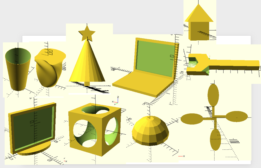
- I created a set of cubes with cylinders on top. I made a method for this object as a default and I then create two more that I scale and another where I resize.
- I created a pair of glasses. I designed 2 cylinders for the lens and the frame which I rotated 90 degrees. I created a method that designed one half the glasses. I then call the mirror tool over the y-axis to have both sides of the glasses symmetrical.
- I created a monitor. This monitor was made using a module which is a linear extrude of a square with a smaller square cut out of it for the screen. I translated it above a linear_extruded circle that acts as a stand and rotated the monitor by 90 degrees to stand vertical.
- I created a laptop. I linear extruded a square for the keyboard and reused the monitor module placed against the keyboard as if it were connected and rotated it 100 degrees.
- I created a cup. I made a cylinder with height of 50, bottom radius of 10, and upper radius of 15. I set the number of fragments to 100 for a smooth cup. I use the difference on the same cylinder shape but translated up by 2.
- I created a fan. I made a module for a fan blade that consisted of a a circle that was resized, rotated, and translated to the end of a cube which acts as the connector for the fan. I then use a for loop from 0-360 with increments of 90 for degrees that are passed into the dy of rotate and a fan object is made.
- I created a vase by importing one of my previous stl files for the vase.
- I created a little house. I created a cube of 2 and centered. I then translated and rotated a cylinder also of 2. I used a union to combine the two.
- I created a dome. I did this by making a sphere. I linear extruded a square and centered it. I used an intersection between the sphere and the square.
- I made a penny trap. I took the difference of a centered cube of length 5 and a sphere with radius 3.1 and a fixed number of fragments of 100.
- I created a Christmas tree. I created a cube for the trunk of the tree. I translated and used a cylinder with a top radius of 0 to make a cone. I translated, rotated, and called a start method found at https://gist.github.com/anoved/9622826 at the top of the tree.
- I made a hexagon bolt wrench. I created a method for the handle that makes a 10×1 square and extrudes it and then a head piece, also another extruded square that is 3×3. I take the difference of the handle with a circle of radius 5 and $fn of 6 for 6 edges. I also take the difference of two polygons containing 3 points, or triangles, to add the edgy look to the wrench.
OpenSCAD Print
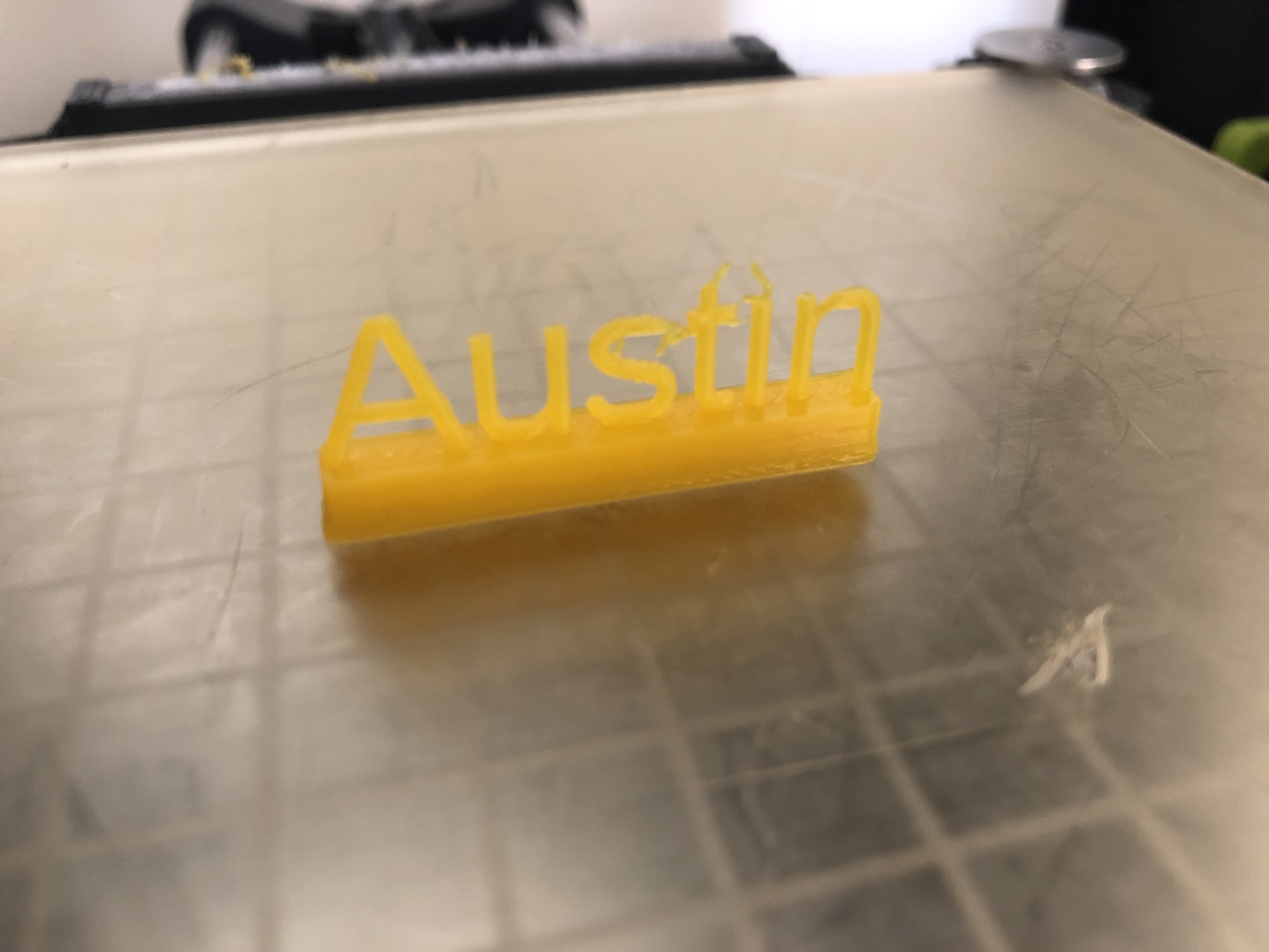
I printed out a name-tag from my 20 openSCAD designs. The name-tag came out mostly successful other than the letter ‘t’. The tip of the letter sort of melted off to the side and made the letter look a little off but is still distinguishable. Like my other prints, I think it would have came out better if I had increased the scale to print out larger.
Summary of Group OpenSCAD Project
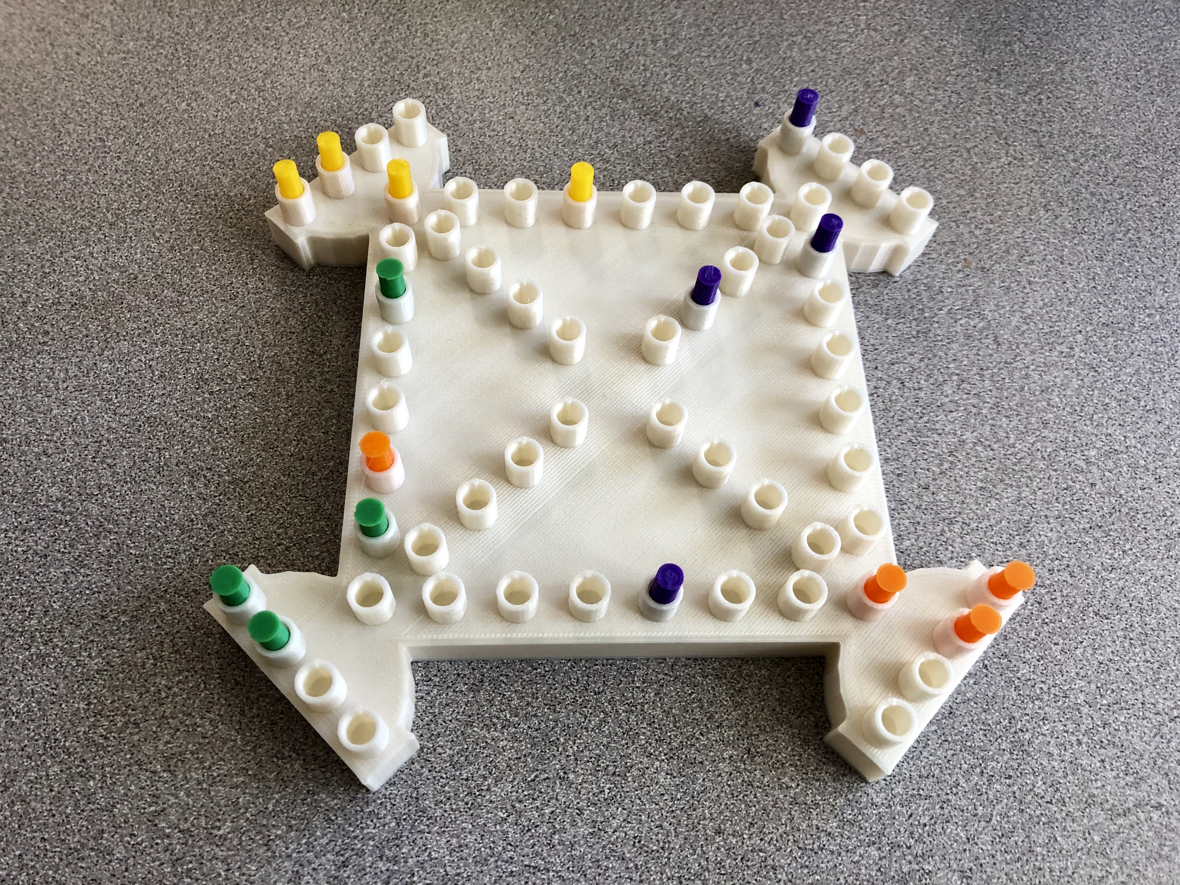
Trouble Board Game(with Ashley Boylan)
https://www.thingiverse.com/thing:3579801
Our project is the board game trouble. The game has 4 players. The board size is customizable, as well as the number of spots, the size of the spots, and the number of pieces for each player. A problem we faced was that the board had to be big enough for the spots/pegs to print out. Once we finally got the pegs to be big enough the board came out perfect. We also made pieces to play the game.
Reflections and Future Projects
I really enjoyed this class and 3D printing. It is different than any other class where we just memorize information and reiterate it on a test. I think I had put a lot more time in this class than average but not because I had to, but because I really wanted to make something cool. I challenged myself to design difficult things and I think the Bridgeforth Stadium and Trouble Board Game for my group project speaks for it. I knew it would hard but was excited to see the final results and they were a success. The class seemed to be amazed by them too. I would say that I liked working on the large group design over the small 20 designs. Also as a computer science major it was great to see how code could be used in 3d printing when using openscad.
What I wanted to do at the start of this semester was do design stuff I could give to my friends. I have designed some things but I want them to be better. I was happy to hear that there are 3d printers available in the libraries outside of the classroom. I find it hard to come up with ideas when I think about them. They sort of just pop up randomly and its good to know I can take that random idea and print it. I would like to possibly design my actual house tho. I think it would be really cool to have a replica and try to make it look as similar as possible.
Overall, this 3d printing class was great. Thanks professor Taalman.